Last month Ken Krueger described some of the initial challenges he encountered while making empennage fairings using 3D-printed molds. This month Ken explains how he optimized the mold design process to significantly reduce the cost of his molds, and he concludes with some pointers on designing your own 3D-printed molds. We look forward to seeing parts our readers make using this technique. Email high-res photos to [email protected]. Please use “3D Printing” as the subject line. Don’t forget to tell us what type of part you made.
—Eric Stewart
Rudder Tip Fairing
The rudder tip fairing, at just over 26 inches long, is more than three times longer than the horizontal stabilizer tip, so in an attempt to keep the cost of the mold set as low as possible, the mold was designed with a minimum thickness of .080 inches. While this may seem rather thin, the Shapeways recommended minimum is .028 inches but with the warning that, depending upon the shape, thin wall parts may warp. The rudder tip fairing has lots of curved surfaces, which could be expected to hold their shape well, plus the minimum thickness chosen was nearly three times the recommended minimum, so theoretically, it should be fine.
My wife, having worked in the aerospace industry as a purchasing agent, is a real stickler for proper part marking and identification. She proposed that the part number be printed directly into the outside surface of the mold. So, in addition to external stiffening flanges and slots for prying molds apart, the part number was printed in raised lettering on each piece of the rudder tip mold.
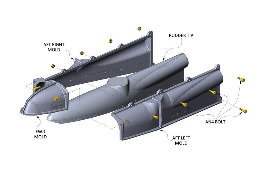
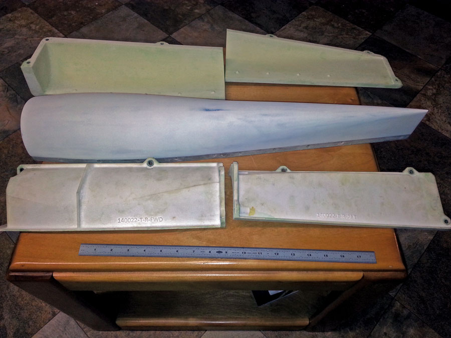
The rudder tip mold was initially designed in two halves, left and right. The size of Shapeways’ print envelope is 25.6 inches by 13.8 inches by 21.7 inches. While the length of the mold was greater than the width of the print volume, it would easily fit if oriented diagonally. Shapeways wasn’t willing to reorient the part and forced a redesign by declaring the mold halves unprintable. The final solution is a three-piece affair: a front mold, a left aft mold, and a right aft mold. By making the aft mold halves just short enough to fit lengthwise in the print volume, the front mold was kept rather short (see Figure 1).
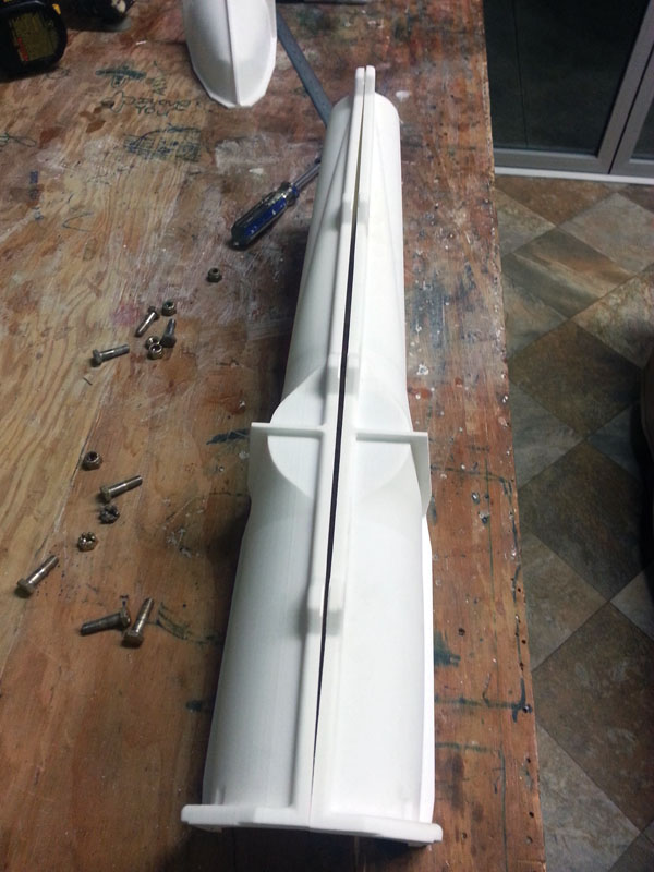
Figure 2: The long, thin rudder tip aft mold halves were warped, but when bolted together, they pulled themselves straight.
When the rudder tip mold set arrived, the false assumptions made in the design process became apparent. As forewarned, the long, thin aft mold halves ended-up with the nice graceful warp shown in Figure 2. Thankfully, once the three parts of the mold were bolted together, they pulled themselves straight and, in the end, yielded useable parts.
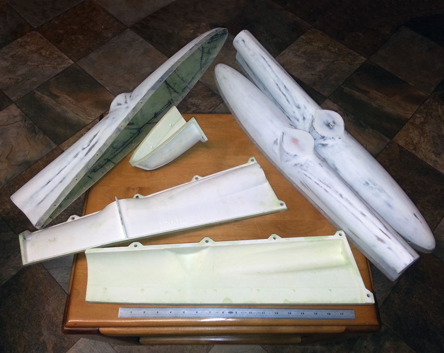
The preparation of the mold, materials used, and layup schedule were the same as with previous parts. Despite being rather thin, the molds showed no damage or wear after producing three parts (see Figure 3).
The complete rudder tip mold set cost $475.39. With a molding surface area of 245.4 square inches, the dollar cost per square inch comes out to $1.94 per square inch.
The lessons learned from the rudder tip are as follows:
Because of the tendency for long and/or thin 3D-printed parts to warp, .080 inch is probably too thin for a 3D-printed mold, particularly one that is over 20 inches long.
If the length of each piece of the rudder tip mold had been kept to about 20 inches, less warpage would have occurred.
Figure 3: The complete rudder tip mold set cost $475.39, which works out to be $1.94 per square inch.
Elevator Tip Fairing
The last and largest of the four parts is the elevator tip. Coming off the “successful failure” of the rudder tip, the elevator tip became an opportunity to apply the experience of the three previous design cycles and produce a set of molds optimized for cost, functionality, durability, and long-term stability.
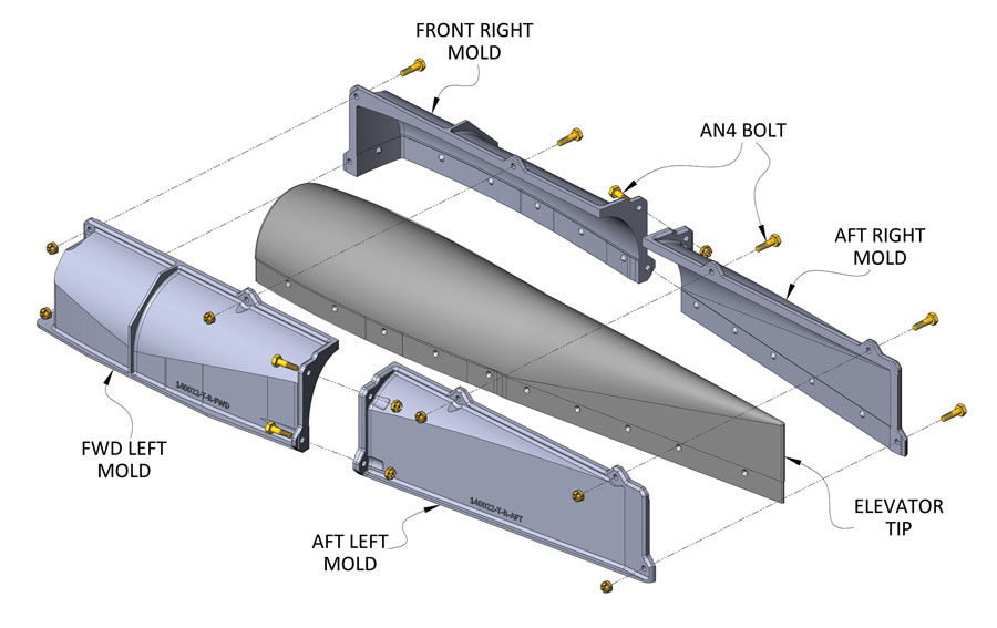
The elevator tip mold was made in four pieces: a left side mold and right side mold, each having front and rear halves. A minimum thickness of .118 inches was chosen as a good compromise between initial cost and long-term dimensional stability. The length of each piece of the mold set is about 14.5 inches.
Stiffening flanges, pry slots, and part numbers were printed into the outside of each piece of the mold. The mold inside surface features sharp, crisp joggles and fastener holes matching the holes in the metal skins to which the part will be attached, and conical recesses at each fastener hole to receive the dimples in the sheet-metal skins (see Figure 4).
Figure 4: The elevator tip mold was made in four pieces. Note the fastener holes that match the holes in the sheet-metal skins.
The complete four-piece elevator tip mold set cost $630.51. With a molding surface area of 450.8 square inches, the dollar cost per square inch of molding surface equals $1.40 per square inch—just over a quarter of what the rudder bottom mold cost!
A total of six elevator tips were produced. As with all the previous molds, no appreciable damage or wear to the mold could be seen (see Figure 5).
Figure 5: The elevator tip mold set cost $630.51. That’s $1.40 per square inch—just over a quarter of what the rudder bottom mold cost (see Part 1 in last month’s issue for details).
Design Guidelines
After four iterations of the 3D-printed mold design cycle, the following design guidelines emerged:
• Stiffening flanges and ribs are a more cost-effective means of stabilizing the mold than simply making a very thick mold.
• The designer should configure the stiffening flanges and ribs in such a way that the mold will be stable as it rests on the work surface. Having a mold that doesn’t wobble or tip over when placed “mold surface up” on a table makes life easier for the person laying-up the part.
• Raised lettering can be printed on the outside of the mold with practically zero additional printing cost.
• The designer should think about how the cured part will be removed from the mold. Provide places for the individual pieces of the mold to be pried apart. Designing with areas of zero draft or tiny areas of negative draft is acceptable, but the part will need to be flexed as it is removed from the mold. Most CAD applications have a draft angle analysis feature that will graphically show areas on the mold that may make a part difficult (or even impossible!) to remove.
• A thickness of .118 inches (3 millimeters) will produce a mold that can be expected to last indefinitely.
• Plan to pay around $1.50 per square inch of part molding area for a mold printed out of SLS Nylon.
Things to Consider Trying in the Future
The 3D printing process produces objects with tiny “layers” or “steps” in their surfaces. The parts in this article were layed-up on the “raw” 3D-printed surface, but it may be better to fill and smooth the mold steps with thickened epoxy. This should produce parts requiring less finish work.
The material data sheet for the 3D-printed nylon states that the lowest Vicat softening temperature is 325⁰F. All the parts produced in conjunction with this story were made with room temperature cure resin, but it should be possible to make 250⁰F-cure pre-preg parts on 3D-printed nylon molds.
Final Thoughts
I hope this article will inspire readers to experiment with 3D printing. If you do, please share your experience. By doing so, we all will be able to take better advantage of this amazing technology.

