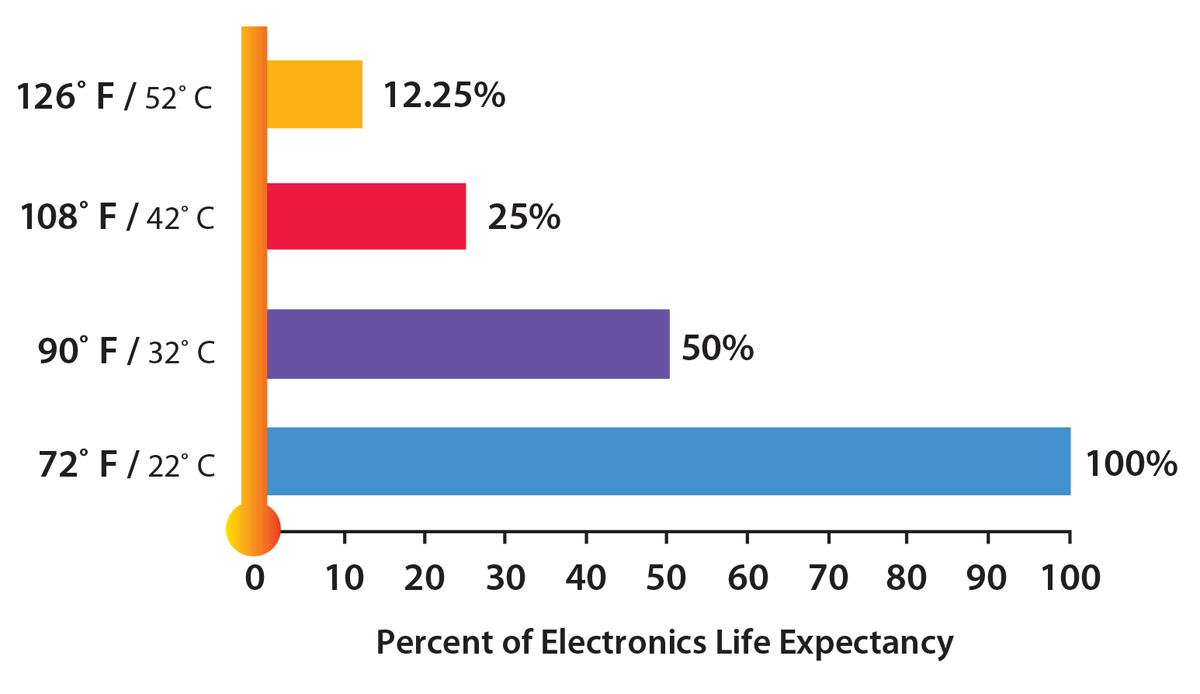
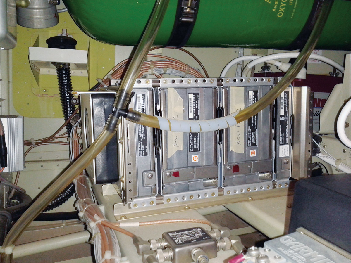
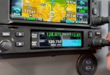
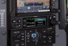
All electrical equipment in one form or another generates heat. Lowering the environmental temperatures in which the electronic equipment is housed, the avionics bay in this case, will extend the mean time between failures (MTBF) of the avionics/electrical units significantly (see Figure 1).
A cooling fan provides a good solution for cooling avionics/electrical units. This in turn prolongs the life of these units. Fans are safe, reliable, easy to install, and an inexpensive way of cooling.
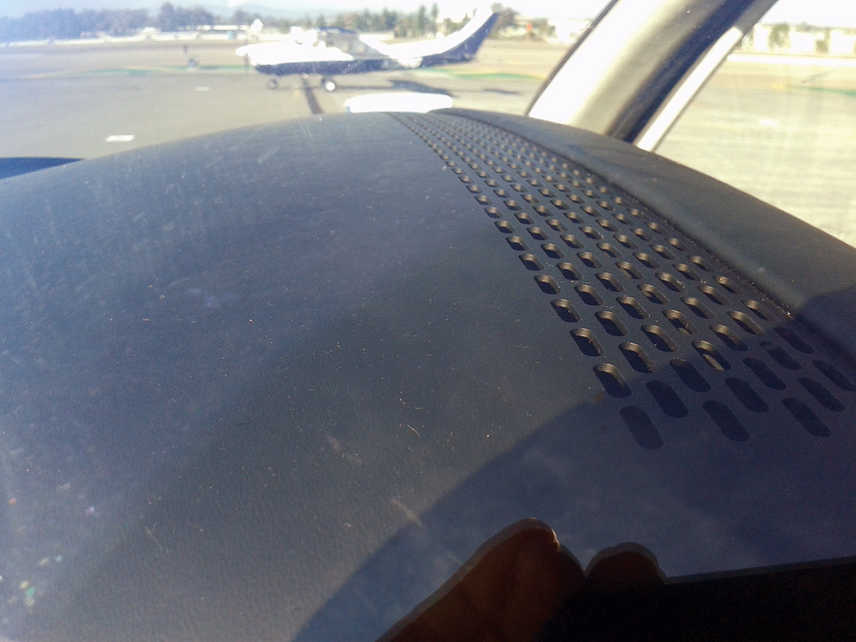
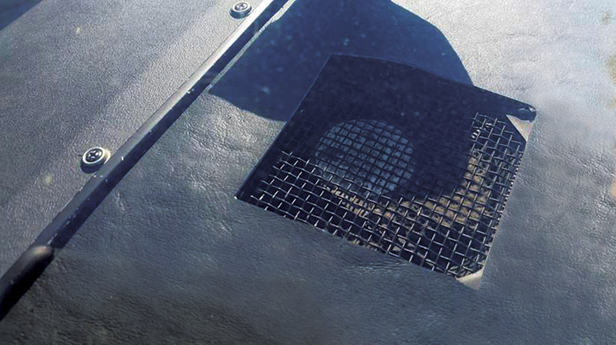
The aircraft I’m currently working on has graphic display units (GDU) for which the manufacturer recommends cooling fans with vents placed in the glareshield behind the GDU. The line replacement units (LRU) either have provisions for cooling or fans have been provided for that purpose.
When dealing with avionics/electrical equipment, you need to determine what size fan is required for cooling or removing heat. I use a simplified method for solving the fan size requirements that consists of four parts: cubic feet per minute (CFM) required to cool, exit opening size, location of the fan(s), and source of air. The fan used in this article was a Lone Star Cyclone 21 DC avionics blower rated at 21 CFM, 24 VDC. The fan has three blower ports, and each port has a half-inch inside diameter.
Advisory Circulars (AC)
A piece of helpful information is an advisory circular. They are not required by regulation; nonetheless, they contain useful information. Here is an excerpt from AC 23.1311-1C, Installation of Electronic Display in Part 23 Airplane, Section 27.0, “Environmental Conditions,” 27.2, “Temperature”:
“Electronic systems reliability is strongly related to the temperature of the solid-state components in the system. Component temperatures are dependent on internal thermal design and external cooling. In evaluating the temperature environment, consider the additional heat generated by the equipment, especially in a location where airflow is restricted. To determine if adequate cooling is provided, your evaluation should make maximum use of previous data from comparable installations, thus limiting ground or flight tests to those installations that cannot be verified conveniently by other means. When the equipment/operating environment cannot be verified from previous experience or from an evaluation of temperature values in that equipment location, a cooling test should be conducted.”
Sources of Heat
The primary adversary to avionics/electrical equipment is heat. There are two sources of heat: the avionics/electrical units themselves and the sun on the glareshield, called solar heat radiation or gain. The hottest temperature the aircraft will endure is when it is sitting on the deck (aka the ground for the common folks) on a hot sunny afternoon, not moving, with all the electrical equipment on.
Find the Watts Needed for Cooling
Sum the watts of the electrical units in the avionics bay. You’ll find this information in each unit’s installation manual. Don’t include the watts generated by the fan(s).
Always follow the manufacturer’s guidelines. If the manufacturer recommends using a fan with a unit, by all means use one. For example, it is recommended that fans be used with the LRUs in our aircraft, and inlets are provided to direct the ducted air to the avionics.
Some of the units like the primary flight display (PFD), multi-function display (MFD), and line replacement unit (LRU) are provided with fans. It is safe to assume that these units can be left out of the equation for solving the theoretical total required CFM if, after cooling the avionics, the air is ducted out of the avionics bay. Otherwise, they should be included in the calculation because the hot air has not been expelled and is only recirculating in the avionics bay. For example, an aircraft generating almost 700 watts from the electrical equipment may only require approximately 300 watts to be cooled.
Determine the CFM Requirement
The first step in finding the fan size is solving the CFM requirements. Start by solving for the differential temperature. For example, having a normal day of 59 F, the equipment has been rated for 158 F. This provides a differential temperature, Delta (Δ) T of 99 F (158 F-59 F). The aircraft just might be sitting on the deck with its interior temperature melting away at 158 F. Would you really want to fly in a plane this hot?
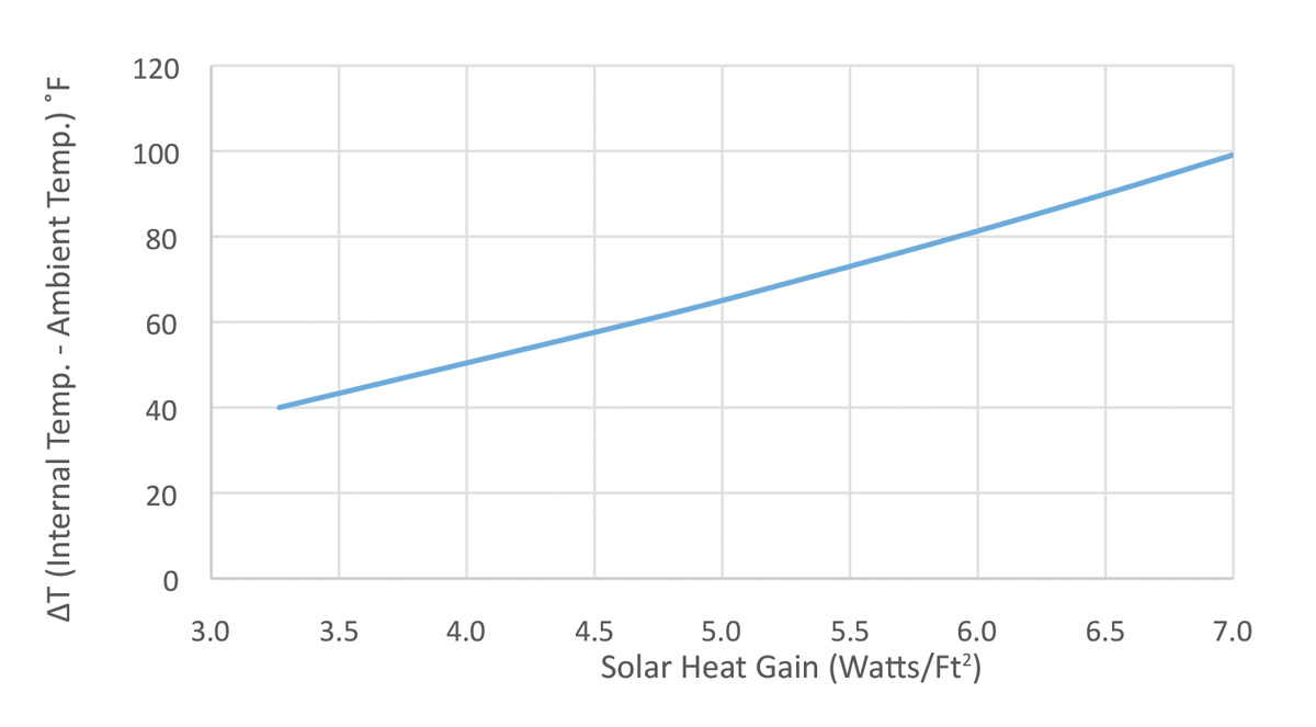
The second step is solving for solar heat gain from the sun. Let’s say an aircraft has a black glareshield, surface area of 944 in2 (6.6 ft2). With a maximum internal temperature of 158 F inside the avionics bay, minus a maximum outside temperature of 120 F, this provides a differential temperature of 38 F. Referring to Figure 2, this will produce about 3.3 watts/ft2 solar load. Multiply this value by the glareshield surface area, 6.6 ft2. This increases the heat to 22 watts. There is a caveat here: This is neglecting any heat loss from the heat transfer from the outside of the glareshield into the avionics bay by the insulation within the glareshield.
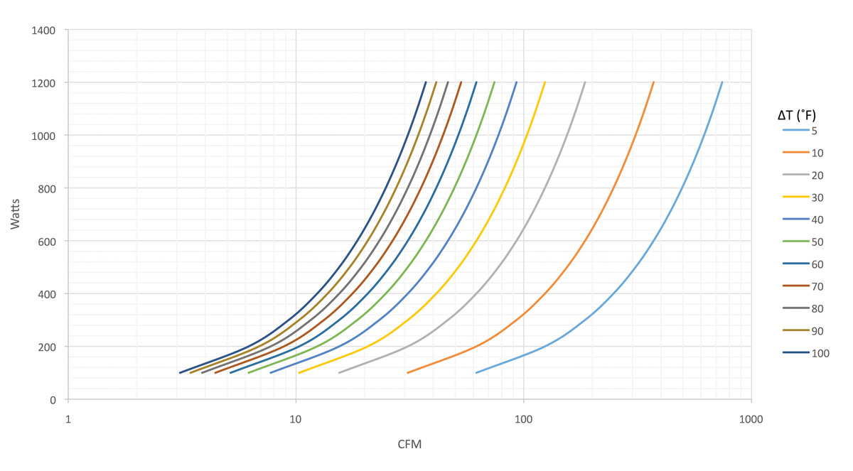
The third step is to solve for CFM. Add the avionics/electrical unit watts to the solar heat gain value, thus becoming 322 watts. Refer to the CFM vs. Watts chart (Figure 3) to obtain the theoretical total required CFM from a fan.
The objective is to have the mass flow rate or CFM generated by the fan greater than the required mass flow rate or CFM required for cooling the avionics/electrical units. If not, the heat will not be dissipated or removed as shown in Figure 4, Mass Flow Rate vs. Delta T. A 21-CFM fan will work just fine to a given point as shown in the example.
When selecting a fan(s), err on the side of caution. Go with a fan or total of fans that are at least 1.5 times greater than the required CFM—more is better in this case. The fan provides the CFM for cooling; the only way to increase CFM for cooling is to have a bigger fan or more fans.
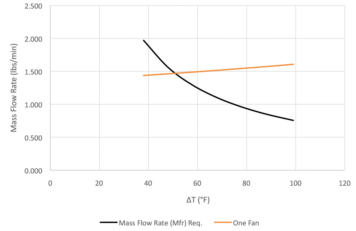
Figure 4: Mass Flow Rate vs. Delta T (F) – Mass flow rate generated by the fan needs to be greater than the mass flow rate required.
Beware: The air velocity needs to stay below Mach speed due to compressibility. Compressibility occurs at high speeds and high pressures. In theory, it occurs around the speed of sound, which is at 661.7 knots (760.9 mph) at sea level and 59 F, although this will most likely occur around Mach 0.3.
Solve for Exit Opening Size
The exit opening is just as important as anything else in the system. The opening has influence over the static pressure. It is one of many things that can cause static pressure increase. Reducing the amount of static pressure increase can be accomplished by designing in the correct size exit opening.
The exit opening needs to be the same size or greater than the entrance opening. The opening(s) can be in a different configuration: holes, slots, rectangles, louvers, etc. with varying sizes. Another question to ask—is there flexibility to change the size of the exit opening?
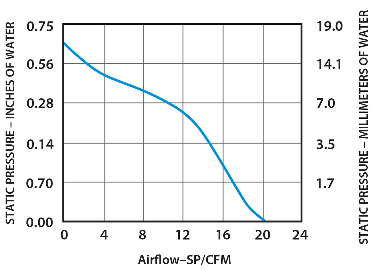
Solving for exit size, use the fan performance chart (Figure 6) to convert static pressure/inches of water to static pressure drop (PSF). Locate static pressure drop (PSF) on Figure 5 to determine exit area (ft2) or vice versa. The static pressure drop (PSF) vs. exit area (ft2) chart is based off standard atmospheric conditions.
Remember, the objective is to keep the static pressure increase or CFM drop to a minimum. For example, a .56-inch water drop from Figure 6 shows the fan is only producing 2 CFM. Is this acceptable for cooling the watts being generated?
When the outlet size is established at sea level, the CFM will vary as the differential temperature increases or decreases as shown in Figure 4. As the differential temperature changes, a greater or lesser amount of CFM becomes available from the fan for cooling. Resize for the worst-case scenario.
Locate the Fans
Where should the fan be located? The thought of strategically placing fan(s) directly on the outside of the heat source(s) might solve some of the problems for cooling. However, the downfall is that the surrounding units are neglected from cooling. Having a main fan for circulating the air flow in the avionics bay is ideal; however, there might not be room for one or the efficiency might not be achieved due to flow obstructions. This might be a sound reason for attaching an exhaust fan underneath the glareshield. Nonetheless, it is easier to circulate the air out rather than to extract the air. Among many other things that can hinder exhaust fan performance is the outside air pressure, which always has to be lower than the inside air pressure or the fan will not exhaust the hot air out.
Source of Air
The primary source of air should be obtained from the cabin air. Very little airflow is achieved from ram air while on the ground. Using outside air or ram air lends itself to ingestion of foreign object debris (FOD) or moisture into the avionics/electrical units, which could cause harm.
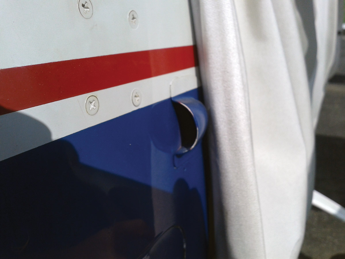
Very little airflow is achieved from ram air on the ground. Ram air can also lead to ingestion of foreign object debris (FOD) or moisture.
Conclusion
This article provides the basics for calculating how much cooling is needed for avionics and electrical units. There are other things that can hinder cooling, such as obstructions and restrictions to the airflow’s path. For a simple solution, use ducting, baffling, or a plenum to direct the airflow where needed.
Check validity of the cooling requirements, then create a prototype for validation; this will determine if the fan selection meets the requirement. Nevertheless, this is only a baseline for determining the proper fan(s) size required for adequate cooling.

