This month’s tip comes from master machinist, Harmon Rocket builder, former Jabiru owner, and Golf Instruments kingpin: Craig Cook of Oceanside, California.

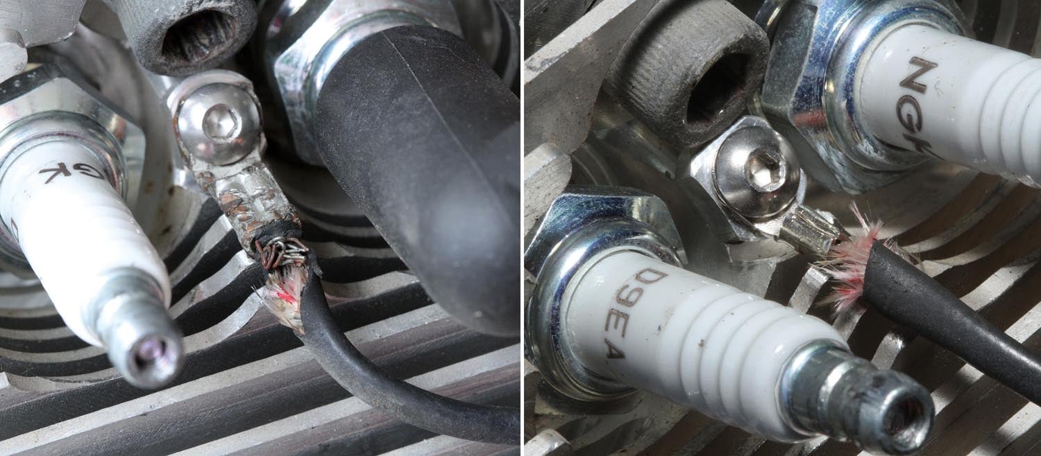
Before selling his Jabiru earlier this year, Craig did the “Cylinder Head Modification for CHT Sensor Installation.” This modification, which was published by the factory in 2013, involved moving the CHT (cylinder head temperature) sensors from under the spark plugs (one per cylinder) to a dedicated spot between the dual plugs.
To quote from the Jabiru instruction, the rationale for modification was: “The spark plug sensor was prone to damage to the thermocouple during maintenance.”
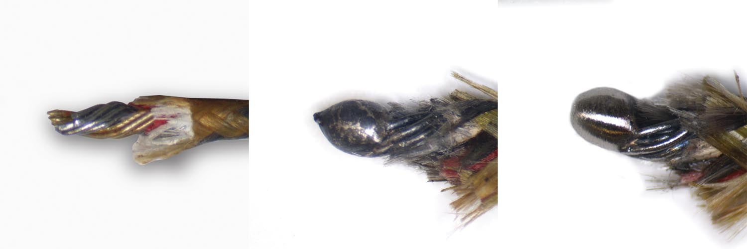
They weren’t kidding! While under-the-plug CHT sensors are common, the spark plug pockets machined into the Jabiru heads are a tight fit, providing just enough room for a socket wrench. Consequently, the tang that encapsulates the thermocouple end (called the junction) is prone to getting bound up and mangled. After just a few plug changes, it’s not uncommon for the wires to get frayed where they go into the tang.
As a fellow Jabiru owner, Craig asked if I had done the modification and if there was anything he should worry about. I replied that I had, that it was straightforward, and that I had also taken the opportunity to replace a couple of badly frayed wires. In fact, most of my CHT wires were frayed to some extent, but the ones I replaced were goners. Since the sensor wires (or probes) are about $20 each, I didn’t change the ones that were still working.
That’s when Craig said, “You know you can fix those. You can weld them with a TIG welder. I’ve welded tons of them.”

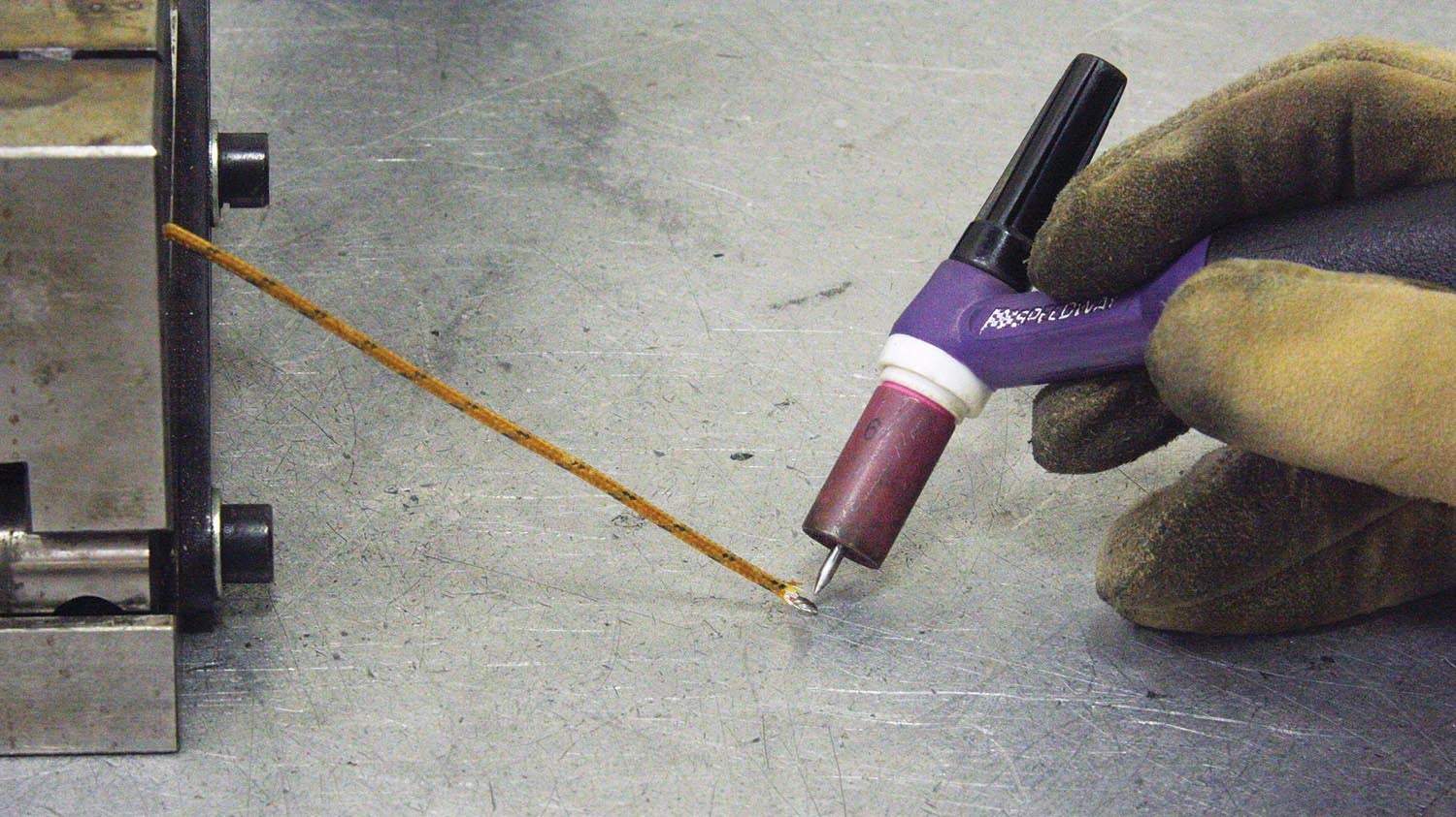
Craig went on to explain that the welder needs to be set at the lowest possible amperage, 5 amps if the welder will go that low, but no more than 10 amps. Clean up the ends of the wires, twist them together, set them up on a good ground, and zap the end with the quickest burst you can give it with the TIG pedal.
I’ve since tried out Craig’s technique, and it works great. It restores the connection at the end of the thermocouple to as good as new.
I’ve read that for certain temperature sensors, the manufacturers caution not to shorten the wires. But according to Eric Bartlett of GRT Avionics, that’s not a problem with GRT’s CHT sensors.
“Thermocouple wire length has no effect on accuracy. Some would argue that it does because longer thermocouple wiring has more resistance than shorter wiring, but a thermocouple’s own resistance does not have any effect on the voltage it generates. A rule of thumb from the industrial world is that thermocouple wiring can be up to 100 feet long. Lengths beyond 100 feet are to be avoided because they are more likely to pick up radio frequency interference. We tell our customers to cut to fit harness wire lengths for individual CHTs and EGTs for a clean installation,” Eric said. “They do not need to be the same length. We have customers who order harnesses anywhere from 6 to 20 feet.”

In any event, after repairing the frayed thermocouples, the CHT readings were identical. If there was any change, it was less than the resolution of my GRT Avionics EFIS, which displays degrees in whole numbers. (According to GRT, they use a J-type thermocouple for the CHT probes, and the accuracy is ±2.5% of reading from -40°F to +333°F and ±0.75% of reading from +333°F to +750°F.)
It turns out that for thermocouples to work, they don’t have to be welded. Twisting or crimping is also used in some applications, which explains why they still worked on my engine even with some fraying. I must admit, however, that running around with frayed wires, working or not, bothered me. Fixing them using Craig’s method not only assured future reliability, it also restored my peace of mind!
Special thanks to Eric Bartlett and GRT Avionics.
![[Credit: Lisa Turner]](https://www.kitplanes.com/wp-content/uploads/2026/02/Fuel-Selector.jpg?w=218&h=150&crop=1 "Fuel Follies")


I have made a number of welds on very tiny wires with my TIG. A much better way than described in the article is to set up the TIG as described at the lowest stable arc. Place the wires to be welded on a 1/8″ or thicker scrap of steel. Start the arc away from the wire to be welded and then walk the arc slowly towards the wire. Before the arc gets to the wires to be welded, you will see a nice weld ball forming at the end of the thermocouple. Release the arc, you are done!
Thanks! I’ll give that a try.
Comments are closed.