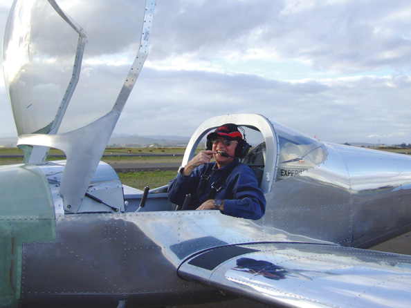
As I write this, the first of the Independence, Oregon, Van’s Aircraft RV-12s (mine) is flying its required test flights after an 18-month building process. Six of the 18 months were waiting for kit segments.
After one more test hop, N812DL moves out of its Phase I category. I will remove the 100 pounds of ballast from the right seat and replace it with the first passenger. My wife, Lois, who weighs slightly more than the sand, may volunteer to be the test passenger. Seven other RV-12s here are being built or are finished. One passed its airworthiness inspection a few days ago and should fly soon. As we went to press in early December, Van’s reports that a total of 14 RV-12s are flying.
Last Pieces Including the Big One
The last installment in this series got us through airframe building and avionics installation. This episode was delayed a month because some components in the engine/propeller package and the fuel tank revision weren’t ready. The big items in the final package are the Rotax 912ULS engine and a special ground-adjustable composite Sensenich propeller.
Construction for this kit segment begins with installation of firewall-forward components including the sealed battery, master and starter relays, fuel pressure and manifold pressure sensors, and the rectifier regulator. With power and electrical parts in place, avionics were energized, and they all worked. The system really is plug and play! Potentiometers on the forward side of the cockpit control board were adjusted for consistent audio levels.
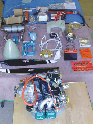
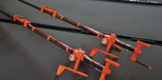
Components of the final RV-12 kit package are ready for assembly.
Included in this subkit are the coolant radiator and oil cooler plus two fiberglass air ducts. One is glassed inside the lower cowl to direct air to both radiators. All or some of the heated radiator air can be directed into the cockpit.
Work on the engine itself starts with preparation for installing the other duct, which directs air down through the four cylinders’ fins. The process begins with removal of everything from the top of the engine: fuel and coolant hoses, electronic ignition blocks and both carburetors. The objective is to trim the duct for a precise fit over the cylinders, and it required an hour working with PermaGrit files and bars. A tight friction fit plus the components that are returned to their positions keep the duct in place. Before the carbs are reinstalled, and drip pans were made and attached, the engine and its mount were joined.
Engine preparation was done in my hangar with the Rotax bolted to its crate bottom. With the preliminaries done, we moved the engine by pickup to the airframe still in the EAA hangar. I borrowed an engine hoist, and in less than 30 minutes, a small group of us had fastened the engine to its home forward of the firewall.
With the big chunk in place up front, the airplane sat on its nosewheel for the first time. This meant it could be moved easily on the airport ramp and taxiway system to my hangar on the airpark side. I chose 11-pp (people power) propulsion, which gave me a chance for first taxi. Toebrakes worked to steer the castering nosewheel, and stepping on both pedals effectively jerked on the propulsion ropes. Anyway, the airplane found its way to its new home.
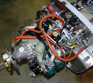
Engine preparation required removing carburetors and other parts to fit and install a fin-cooling shroud. At the lower left is the pitot tube, which is fixed and runs through the gearbox, prop hub and spinner.
Spinner and propeller installation were next. The spinner is fiberglass and must be trimmed, and cutouts for the prop shanks were carefully made. The removed pieces were saved for filling the gap behind each blade. Before prop installation, the unusual pitot tube is positioned through the engine gearbox to a fitting that bolts to the rear of the gearbox, which is on top of the engine. A short rubber tube connects the pitot tube to the plastic pitot line that was routed through the firewall. The spinner and prop rotate around the stationary pitot tube.
The spinner backplate and rear prop hub bolt to the engine prop flange, and the pair of 2.5-pound prop blades are captured by the rear and front hub halves. A diagonally slotted pitch cylinder assures that both blades rotate to the same angle when the pitch is set. The instructions say to set pitch to the coarse end of the range.
For security, I recommend that at least two people help with this operation until the front hub is loosely bolted. You don’t want to drop a prop blade on the hangar floor, and we didn’t. The front spinner plate is attached ahead of the prop hub. A total of 18 nutplates are riveted to the flanges on the two spinner plates. Sensenich recommends torquing the six bolts to 240 to 265 inch-pounds. I’ve justified the purchase of a good torque wrench, as I’ve reset prop pitch several times. No. 8 screws and nylon washers fasten the spinner in position. I labeled “A” and “B” blades.
Lower spark plugs are removed to eliminate cylinder compression, and we set up a way to observe movement of the pitot tube as the prop is rotated by hand. Because the plane is on its gear, I lowered the tail long enough to place a wood block under the nosegear nut. I used a photo tripod with a pointed marker to detect any pitot movement as the prop is rotated. You don’t want any, as it would indicate that the spinner is off center. A tolerance of up to 1⁄16 inch is allowed. I could not detect any movement. Then using the tripod arrangement in a different location, I checked prop-blade tracking. Up to 1⁄8 inch is allowed, and I could not detect any error. Without the nosegear nut on the solid block, both tests would have falsely indicated movement.
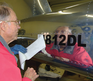
The author applies N-numbers.
Exhaust-system parts were bolted to the four cylinder outlets, and each flue was spring-mounted to the muffler to allow movement. RTV is applied to spring contacts and inside the springs to extend their lives. CHT and EGT probes were wired into the system.
Next came installation and hook-up of the cooling systems, both oil and antifreeze. The large radiator is bolted to the left side of the firewall, and the external oil tank mounts just forward of the battery on the upper right side. The oil cooler lies behind the large air scoop inside the lower cowl, and it is detached from the scoop each time the lower cowl is removed. The lower edge of the cooler is captured against the scoop by cone-shaped standoffs that engage a pair of slots in the bottom of the cooler. Two easily removed AN3 bolts at the top of the cooler join the cooler to the scoop.
For cowl-off first engine runs I used safety wire and a piece of wood to hold the oil cooler in position temporarily. With the lower cowl in place, I found that a 2×2 about 4 feet long could be used to go through the cowl’s bottom air exit to position the cooler over its capture standoffs in the cowl. I needed to be on my back under the airplane to do this, but visibility was good and the procedure wasn’t difficult. It will be necessary for 100-hour and annual condition inspections.
I used a special engine oil recommended by Rotax and Shell Dex-cool antifreeze mixed 50% with distilled water. Pressurizing the systems by turning the prop by hand (lower plugs out) worked to get oil and antifreeze where it should be. Then heater door, throttle and choke controls were hooked up.
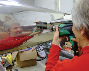
Lois Martin rivets the data plate in place.
Coming to Life
First engine runs were in my back yard with chocks and the tail tied to the base of a fence post. My next-door neighbor and EAA Tech Counselor Ernie Moreno helped with the runup. Turning on the master and avionics switches showed pressure from the electric fuel pump. I turned on the ignition switches, and pulled the choke out an inch and locked it. Engaging the start key cranked the engine, and oil pressure came up immediately. In a few seconds, the Rotax sprang to life for the first time since its factory run in Austria.
Using an electronic carb-balancing tool eventually resulted in a smooth idle at just above 1400 rpm. Pressures and temps appeared normal, but getting the CHT high enough (122° F) to allow engine revs above 2500 took nearly 20 minutes. (Later, with the engine cowl on, warmup was much quicker.) At the end of engine startup day, I taxied gingerly to the airport transient ramp without the cowl, finally got the oil temperature to 122° F, and selected full power. Top static rpm in no wind (it matters) came up to 4720, somewhat short of the recommended range. Several changes later, I flattened the pitch some and got static rpm slightly above the range but decided to leave it, figuring I could throttle back to stay within limits in the air. As it turns out, the last setting was about right.
Placards
The final package from Van’s includes manuals required with an ELSA. The maintenance manual is about a third of an inch thick, and the flight-training supplement is only slightly smaller. Also included was a placards package including the 2-inch EXPERIMENTAL sign, notes about non-compliance with certified aircraft standards, plus labels for controls and canopy entry. I engaged a local sign maker to make the 3-inch vinyl N-numbers, which we attached to the sides of the fuselage, and we had the supplied stainless steel data plate engraved for $15. Lois riveted it in place.
The placard taking the most time was one to be placed on the fuel tank sight gauge, warning not to take off with the fuel below the 4-gallon mark. To locate the placard with its ominous arrow required measuring the quantity and marking the 4-gallon level. Calibrating the electric float-type fuel level sensor with the Dynon EFIS fuel readout requires adding 2 gallons at a time. After locating the 4-gallon point, I continued to pour 2 gallons each time and let the computer do its work until 16 gallons was reached. The process consumed most of a morning.
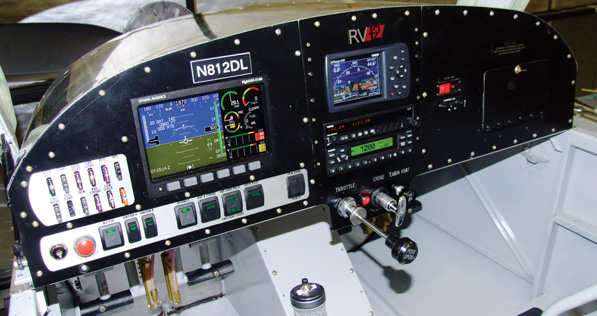
With battery power available, avionics light up for the first time. The Dynon D180 comes programmed for RV-12 limits such as temperatures, pressures and airspeed indicator markings.
The Confession
First taxiing revealed that the Dynon magnetic compass with its remote magnetometer sensor wasn’t working properly. The problem was that I had installed the magnetometer upside down! Denial didn’t work, and the fix used up a large part of one day. The magnetometer is attached to the top of a fuselage ring one station behind the fuel tank/baggage area. To get into this space requires removing a cover plate, and that requires removing the fuel tank. The first step was to drain the 14 gallons of fuel, and that took nearly 2 hours even with the airplane’s electric pump working its little heart out. Supplemental feeding of the battery with an external charger helped.
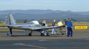
With the engine (but not the propeller) attached to the airframe, the author taxies to his hangar with the help of some friends.
Fuel supply and return lines were disconnected through two inspection holes in the fuselage bottom. Fittings on the tank bottom extend through the floor, requiring that the tank move a few inches vertically for removal; it can’t slide sideways. That required removing the fuel filler neck, which was screwed to the fuselage side and fuel-proofed with tank sealant. Oh, boy.
Lying on my back on some cardboard inside the tail cone, I drilled out the four rivets holding the magnetometer brackets to the fuselage ring. Repositioning and riveting the sensor’s brackets took only a few minutes, and the compass works fine now.
Paperwork
We reserved our N-number a long time ago, and I recently applied for registration. When our registration showed up on the FAA’s web site, I asked the nearby FAA FSDO for the airworthiness inspection, noting that I’d not yet received the actual registration paper from Oklahoma City. Initial contact with the local FAA plus paperwork from Van’s Aircraft made clear what the inspector would need.
Moreno and I used the EAA chapter’s calibrated electronic aircraft scales to determine weight and balance. The nearly paintless RV-12 weighs 716 pounds including firewall-forward fluids plus the pilot operating handbook and fuel sampler in the map case as required by Van’s Aircraft.
The FAA set a date for inspection, and I sent the inspector a program letter plus copies of the registration request, the covers of the training and maintenance manuals and production acceptance procedures, a bill of sale for the kit, a form from Van’s certifying compliance of conformance with ELSA standards, weight and balance data and sample loadings, a photo of the aircraft and a copy of the registration card, which arrived from Oklahoma City just in time.
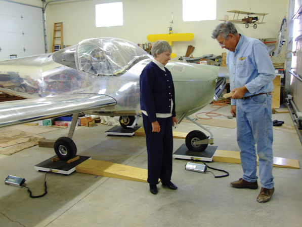
Lois watches as neighbor Ernie Morano checks the scales. Letting air out of the nosewheel tire leveled the airplane for its weight and balance data.
I set up a display table with the huge builder manual, some revision papers, the actual manuals for which he had seen covers, and the originals of papers received in my package. The cowl and the tail fairings were off, and inspection holes were open. The inspector wasn’t pleased with one of my safety-wiring chores (I replaced it), and had a few comments about preventing wire chafing, but he complimented the overall project and gave me a copy of the airworthiness certificate. Stapled to it is the signed Experimental Operation Limitations letter that defines the Phase I test area (the 30-nautical mile radius I requested) and prohibits banner towing and parachute jumping from the airplane. Oh, well. The process was quick and pleasant, and suddenly we owned an actual aircraft, not just a collection of airplane parts fastened together with 13,000 rivets.
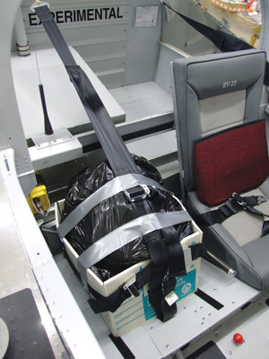
Test flights two through five require increasing the gross weight to 1050 pounds, accomplished here with 100 pounds of sand constrained in the passenger’s seat.
Flight Readiness
More work was needed to get N812DL ready for its even bigger day. The cowl had never been on with the airscoop and its flexible cowl seal. And there were a lot of inspection plates to attach. Weather moved in during this phase. A day of rain was followed by two and a half days of considerable south wind. I was unwilling to take off on Runway 16 because it points at residential Independence. But shortly after noon on the third day, the steady south wind switched to a 3-knot north breeze. Let’s do it!
I had alerted a small group of neighbors that at some point Lois and I could use some help with the first test flight and its long list of required data. With fuel at the 14-gallon level and the right seat empty, I taxied to the airport ramp as members of the volunteer group assembled with several handheld radios and a clipboard copy of the test plan. I planned to use a discrete frequency for the test points.
As the oil temperature passed through 122° F, I taxied to the runup area and ran through the preflight procedures in the pilot handbook, which include an ignition check of each set of plugs at 4000 engine rpm. The drop on a single system was less than 100 rpm, and everything was in the green. It was time to do this.
Flight
As in the red prototype RV-12 I’d flown five months earlier, I found immediate rudder effectiveness on the takeoff run. In a few seconds I was past the recommended 40-knot rotation speed, and the plane ascended immediately on pitch up. Revs were below the 5800-rpm (5-minute) limit, oils and pressures were in the green, and a bit of right rudder kept the electronic version of a slip/skid ball in the center.
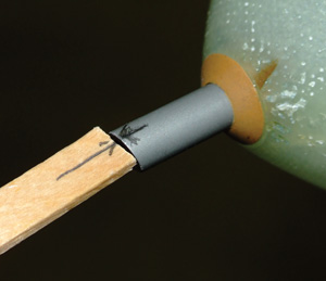
This setup tests for spinner centering by turning the prop by hand and looking for little or no pitot tube displacement.
The only surprise was the need for considerable forward trim to relieve stick pressure. I’ve since reprogrammed the green takeoff trim mark on the Dynon screen. I announced switching to the tactical frequency.
A quick summary of the flight: The radio setup worked perfectly as I read data to the ground. Test Card No. 1 has 73 airborne items to check off. They were recorded, and I was on a full-flap, 54-knot, idle-power approach 38 minutes after takeoff. With wind down the runway at less than 10 knots, the landing was a squeaker, and I turned off at the first runway exit. Everybody else was as pleased as I was.
At this point I have finished four of the five test cards. Completion of the rest will happen when there is a break in the weather. Tests two through five require ballast in the right seat. Three separate double-bagged plastic sacks of sand total nearly 100 pounds and are confined in a box secured with the seat belt and harness.
I’ve climbed to 10,000 feet on three of the test flights. The climb rate is better than the pilot handbook numbers, and the cruise speed is a few knots slower. I need to increase prop pitch a little.
Because this RV-12 is registered as an Experimental Light Sport Aircraft (ELSA), the Phase I test period is complete when the test flights are done and the flight time accumulated is at least 5 hours. In a few days, passengers will get to fly in our RV-12. Guess who the first one will be.
For more information, call 503/678-6545 or visit www.vansaircraft.com.
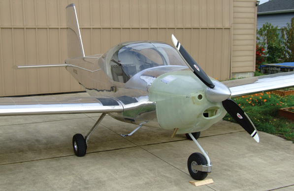
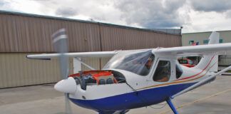
Silver cowl paint and vinyl graphics will come later. This RV-12 is ready for its first flight.

