We’ve finished the structure, installed systems, and have a fine jet sitting there in the shop. Now it’s time to do the final work to get it ready for inspection…and first flight!
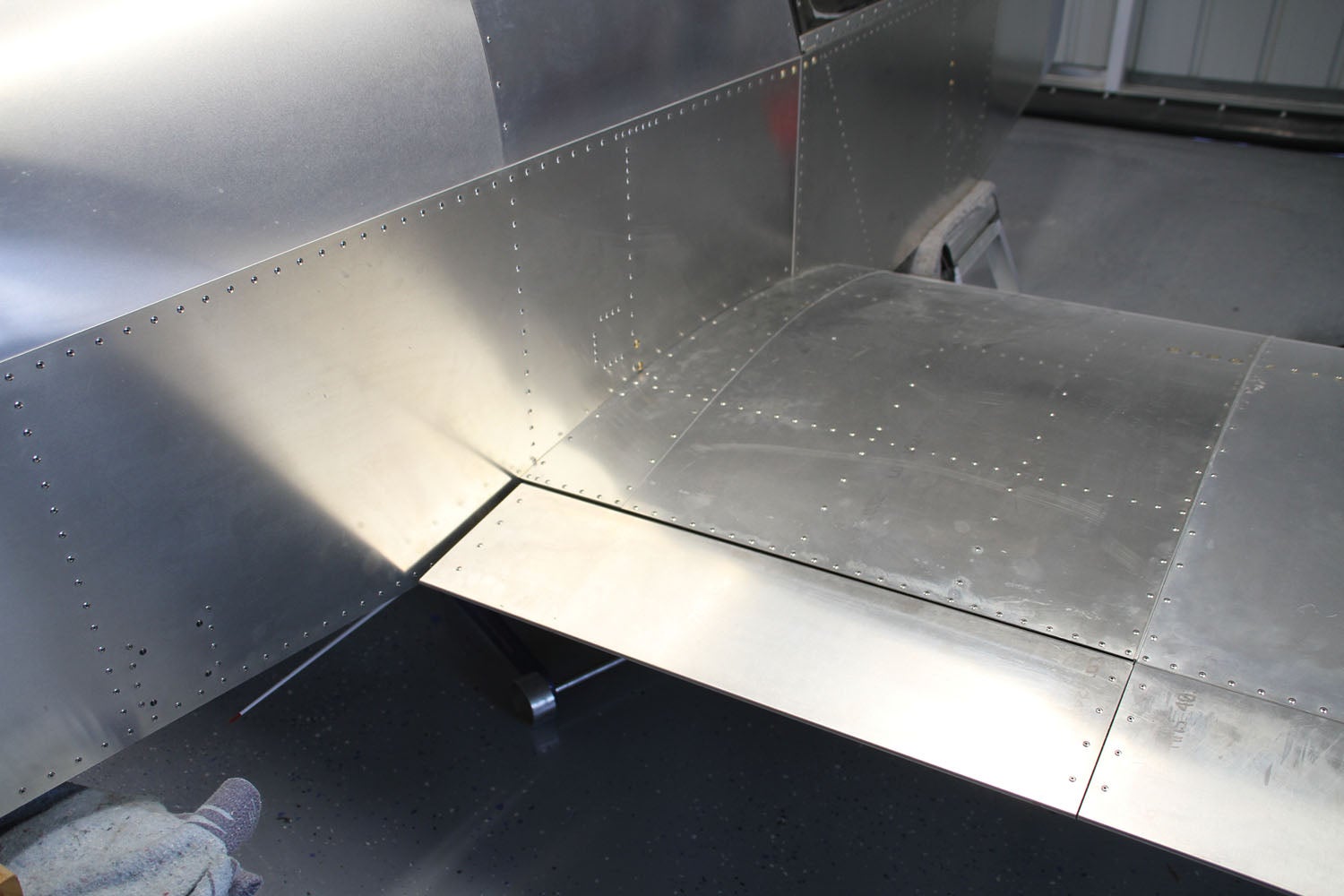
![]() One of the neat things about working on the SubSonex is that the wings are easily removable. That makes it easy to work on in a small space—just leave (or take) the wings off. In the case of our build, we never even installed the wings until the fuselage and systems were finished and working. It was more convenient in our shop to keep the fuselage out of the rigging bay (and leave room for another airplane). There was always, of course, that little guy’s voice in the back of our heads that kept asking the question, “Are you sure the wings will fit?” But we had faith in Sonex and stuffed a shop rag in the little guy’s mouth—and crossed our fingers.
One of the neat things about working on the SubSonex is that the wings are easily removable. That makes it easy to work on in a small space—just leave (or take) the wings off. In the case of our build, we never even installed the wings until the fuselage and systems were finished and working. It was more convenient in our shop to keep the fuselage out of the rigging bay (and leave room for another airplane). There was always, of course, that little guy’s voice in the back of our heads that kept asking the question, “Are you sure the wings will fit?” But we had faith in Sonex and stuffed a shop rag in the little guy’s mouth—and crossed our fingers.

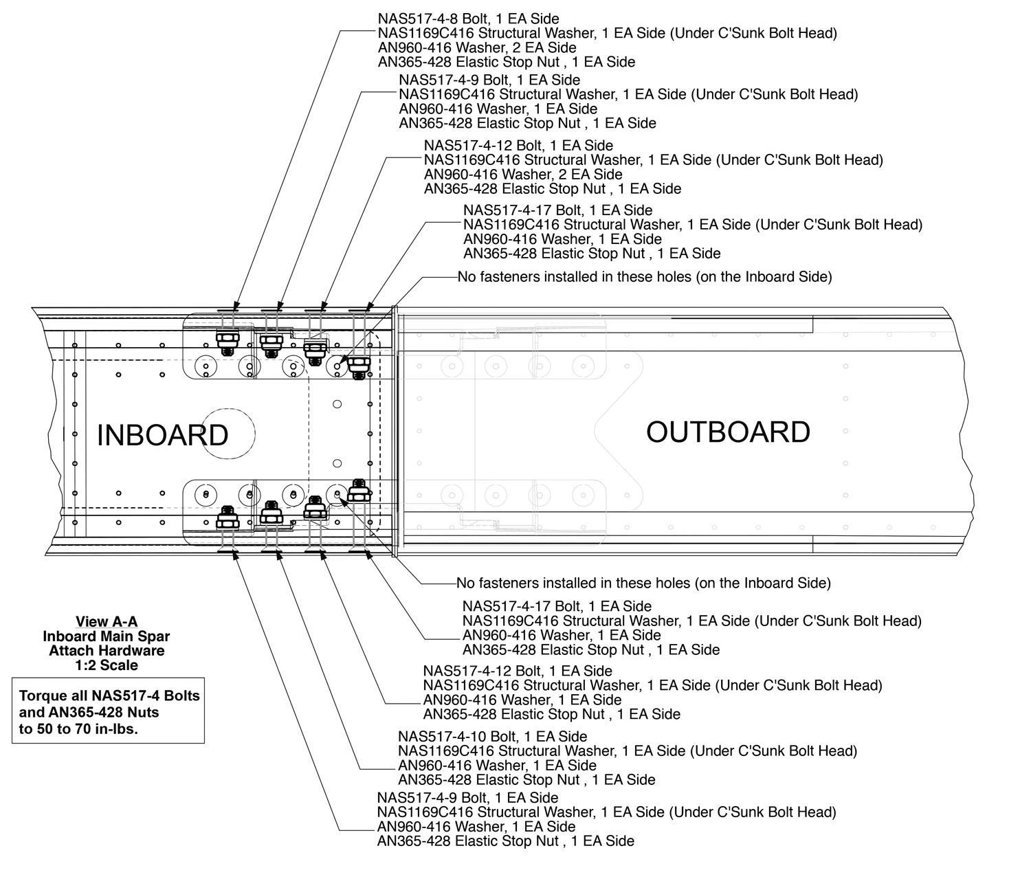
The day we installed the wings, it turned out to be a non-event. Two people, 30 minutes, and it was done. Well, except for having to pull them off again to adjust the length of the aileron pushrods. But the wings slid right in, as if they had been there before—because, of course, they had (at the Sonex factory). The main spar splice bolts are different sizes, based on location, and are different top and bottom, so we made labels out of tape near each hole to remind us which size went where—but it turned out to be fairly obvious. Lining up the outboard flap drive pins took an extra 30 seconds, but once they were in place, the wings slid into their final positions smoothly and solidly. The rear spar splice bolt goes in with the flaps fully down, and all we had left to do was torque all the bolts and connect the wires for the wing tip lights.
Tweaks
With the wings in place it was time to start rigging (adjusting) all of the flight controls. We had previously centered the rudder pedals with the rudder and adjusted the cable tension to what seemed about right. There are no specs given for this, just a note that there should be no slack—so we tightened them up until they were smooth and safety wired the turnbuckles that are just forward of the seat. I admit that with today’s emphasis on pushrod controls, it had been a while since I’d safety wired a turnbuckle. But that’s what AC 43.13 is for—a good reference to have in the shop!
With the rudder pedals centered, it was just a matter of varying pushrod lengths to get the necessary travel for the ruddervators. To make sure that I don’t miss an adjustment or forget to tighten a jam nut, I always torque stripe connections when I am satisfied that they are correct and tight. All connections should have a stripe when the airplane is ready to go—and no torque stripe means I haven’t finished something.
Usually, when I am adjusting control surfaces for correct travel, I use an electronic level zeroed at the straight-and-level position. Deflect the surface up, then down, and you can easily tell if you have the necessary travel. This works great on conventional wing and tail surfaces that are either horizontal or vertical—but the SubSonex has a “Y” tail, so you don’t have accurate angle measurements this way. Instead, I made templates out of cardboard that gave me the up and down limits and used those to make sure the travel was correct.
Flap travel is easy to adjust—you want the top of the flap to be in line with the straight part of the top of the wing skin for the up position, and you get as much down as possible—that’s just mechanism geometry. With the flaps adjusted, you can move on to the ailerons, which proved to be a bit more problematic. Remember that the jet is very tiny, and all of the mechanical movements are small, with small sweep angles. Minor adjustments make a big difference—and there isn’t much motion to play with.
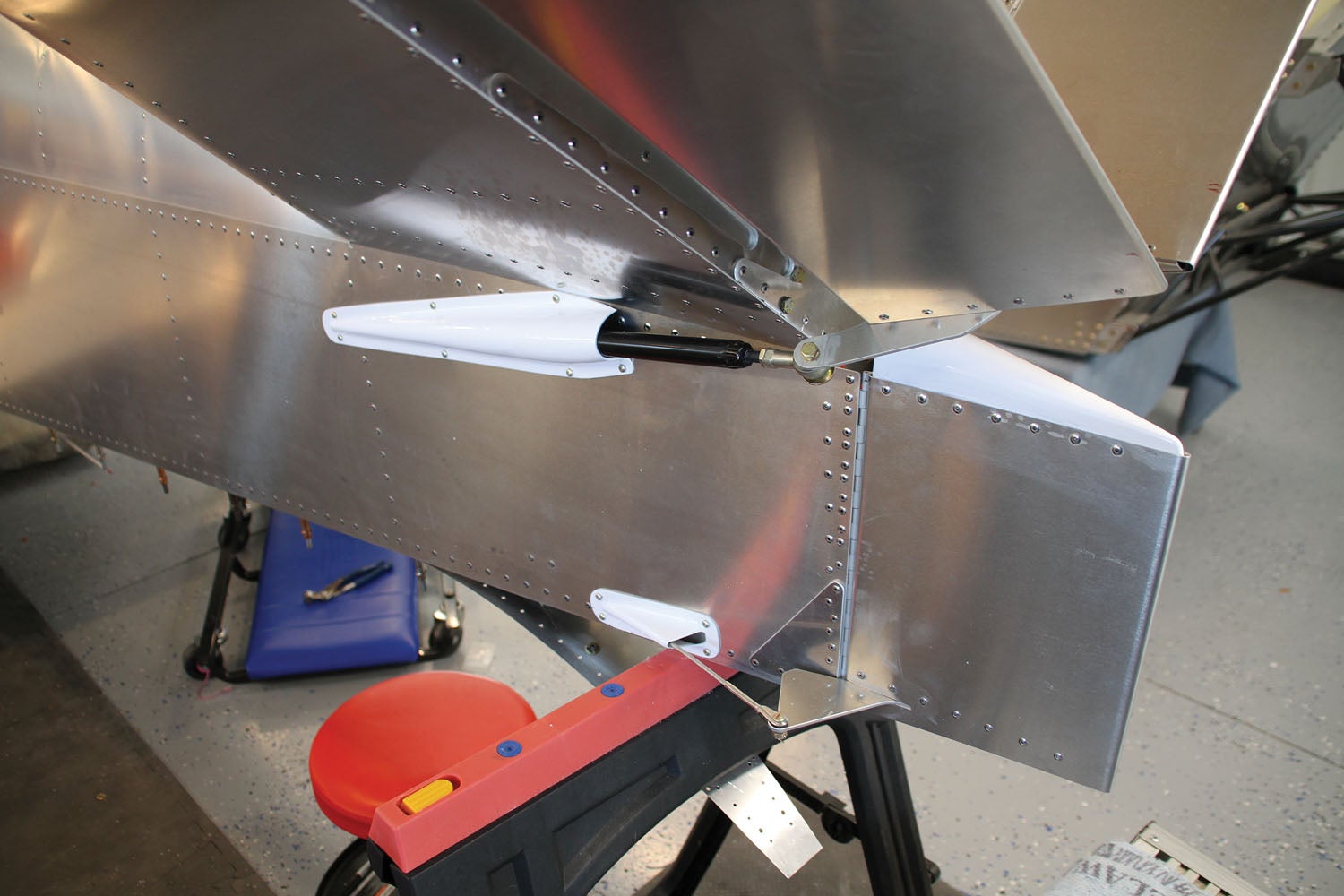
The aileron balance weights are inside the wing, and it turns out that the limiting factor for “down” aileron is when the balance weight hits the inside of the upper wing surface. Fortunately, someone did their geometry, and this turns out to be right at the designated travel limit. But when the ailerons are linked, the “down” travel of one side limits the “up” travel of the other—yet the “up” travel is supposed to be about twice the “down” travel. What this means is that it is very critical where, in the angular deflection of the aileron bellcranks, the ailerons are centered.

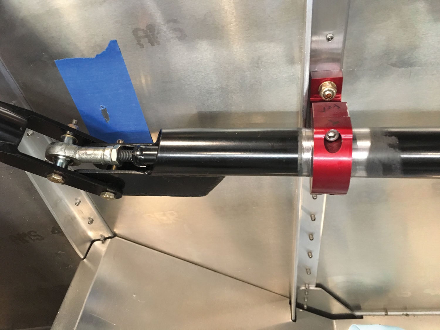
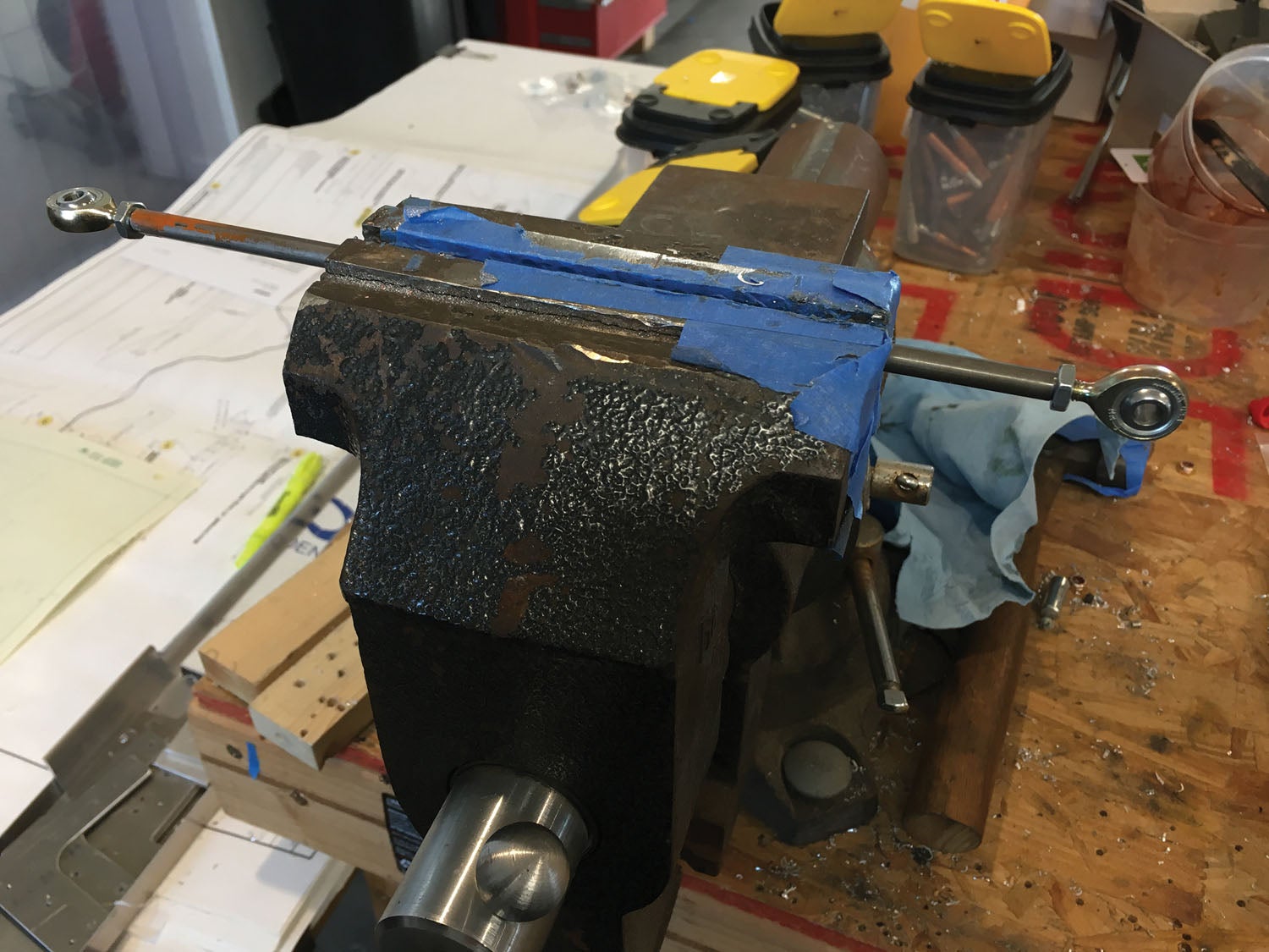
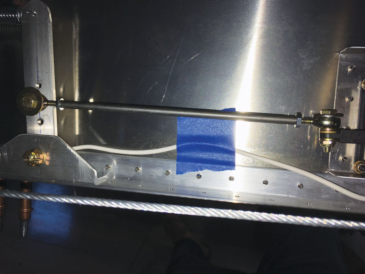
You have to play with the geometry a bit to realize that the movement of the short aileron pushrods is not linear with the movement of the long pushrod (that goes to the stick). This is a function of the fact that the attach point of the short pushrod is actually moving in a circular path—it’s all about trigonometry. After puzzling over this for quite a while and consulting with the factory, we found that the rigging instructions in the drawings were in error when it came to the bellcrank position for “neutral” aileron. What we needed was for the “up” aileron position to be when the bellcrank was pulled as far toward the center of the fuselage as possible—and in order to make that happen, we had to shorten the long pushrods more than they could—at first—give us. Fortunately, the problem was not that the steel tube was too long—it was that the threaded end was longer than necessary, so the Heim joints could only screw on so far—leaving a lot of threaded rod sticking out. Cutting about a half inch off of each end gave us what we needed, and eventually we had the necessary aileron travel. The process, of course, is iterative and takes some tinkering to get it right.
Now, in order to pull the wings, you have to disconnect the aileron pushrods in the belly—there is a special hatch you open to do this. But it is tight in there, and once you get things connected up for good, you might decide just how often you want to pull the wings off! This is not an automatic-connecting sailplane. But to be fair, once you figure it out and have the right tools on hand, it only takes a couple of minutes. It’s the learning curve that is steep and leaves a scarred impression about this in your mind.

Finally, once you have all of the control surfaces moving the way you want, you might make a few minor tweaks to the fore and aft stick position (centering in roll will be a function of where the ailerons end up), but this is done easily from the cockpit, and no floor creeper is required. We did discover that the stick itself could not go far enough forward (at first) to get full “down” elevator, so once again we had to shorten the threaded portion of a pushrod (in this case, the stick-to-mixer pitch pushrod) in order to screw the Heim joints on far enough to shorten the stick sufficiently to get it to work. It is also worth noting that the supplied stick was originally designed for nothing more than a bicycle grip, so if you are going to use the (supplied) “fighter pilot” grip, you need to shorten the metal stick itself, or the top of the plastic grip will contact the panel switches.
The Little Things
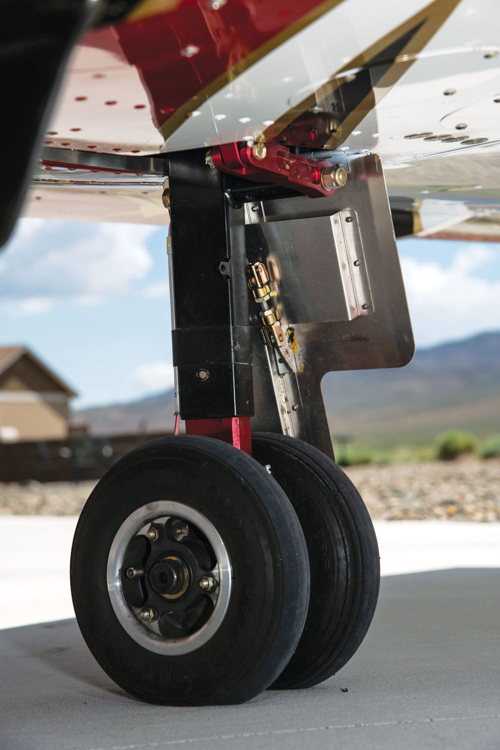
Our jet never sat on its own wheels until very near the end of the build. This was because it was so convenient to have it on the solid workstands and also because it took a handful of neighbors to lift it up and down. It was also nice to have it on the stands so that we could regularly cycle the landing gear. Let’s face it, the gear really needs to work—at least in the “down” direction—and the best way to make sure you are comfortable that this will happen is to cycle it a lot during building. It pays, of course, to not be too casual—always check to make sure some air hose or electrical cord hasn’t snagged on the gear before throwing the switch—but if you do it enough, you’ll learn that.

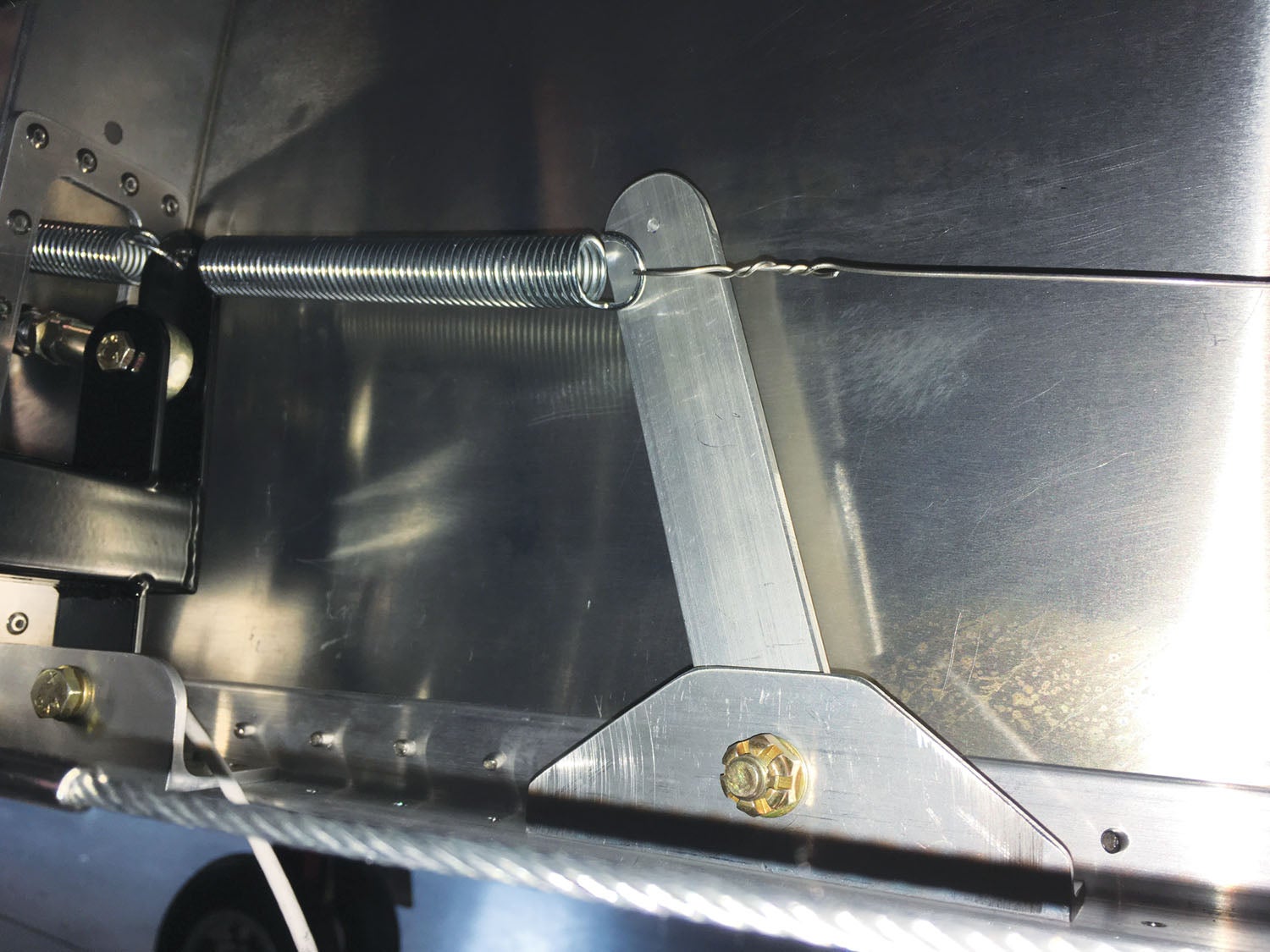
We left the nose gear door off until very near the end, partly because every time we looked at it, we couldn’t figure out how we were going to stretch the spring that pulls it closed. It’s a short, stout little spring, and it attaches to a bolt up in the nose wheel well, as well as to the door. The nose gear has a Delrin bumper that contacts the door and pushes it open as it deploys. The door springs close when the gear goes up. When there was little else to do on the jet, we finally tackled this little project, and it turned out to be simpler than we expected. We loosened the bolt up in the nosewheel well and hooked one end of the spring to it. Then I grabbed that big, stout safety wire—the stuff we have but rarely (if ever) use on light airplanes—and twisted several strands with a loop in one end to hook on the spring, and on the other, a loop to attach a handle (actually, a big screwdriver). Then all I had to do was pull on the handle with most of my weight to stretch the spring and hook it on the door—it turned out to be easy.
The first time you retract the gear with the nosewheel door in place, expect a surprising loud and sharp bang as it closes. I hope I get used to that in flight! The first time we deployed the gear with the door in place, we got a shocking disappointment—the nose gear hung up. Looking at the situation, it was obvious why. There needed to be a bit of a taper on the Delrin bumper attached to the nose gear. Conveniently, the deploy attempt had left a mark in exactly the right spot where it contacted the door, and this showed us where to start the taper. Problem solved.
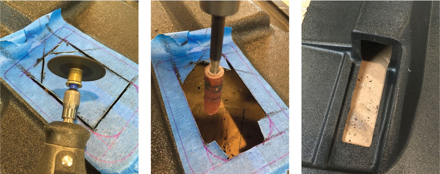
While fooling around with the landing gear, it was also the time to fill and bleed the brakes. After much puzzling over a manufacturing problem that left a couple of the brake pucks (and therefore the brake line) isolated, and drilling the appropriate holes, we were able to pump hydraulic fluid from the bottom all the way to the master cylinder in the cockpit. A single lever actuates both left and right sides, and for a while in the bleeding process all you seem to do is shift the air bubble from one side to the other. But with enough patience we eventually got firm brakes on both sides, and the job was done.
Powering Up
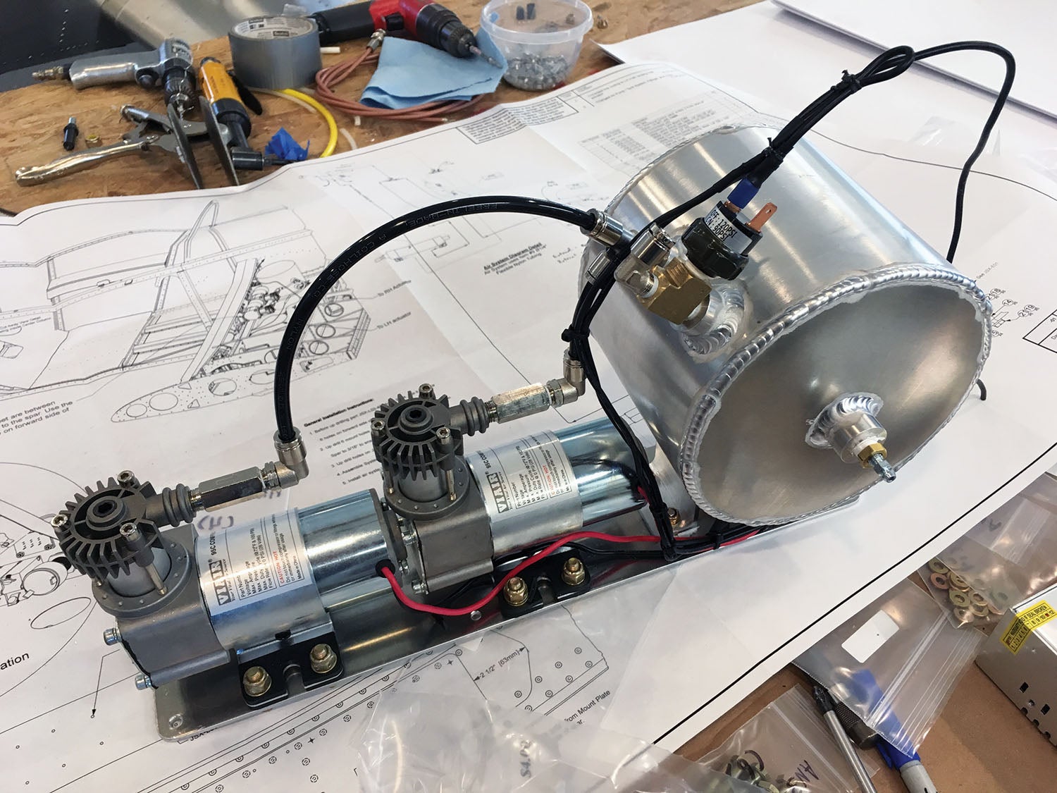
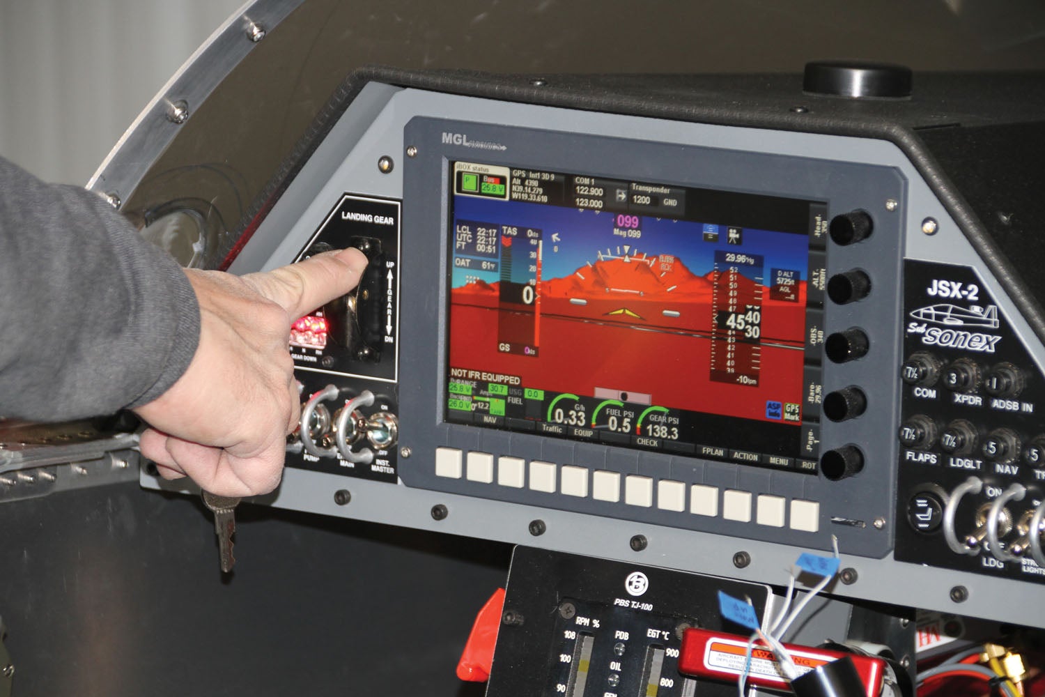
We, of course, were applying power on and off during the build to various components and systems, testing the air pumps, lights and power systems—but it wasn’t until we got to the stage where we could sit in the cockpit and make whooshing noises that we rarely did full-up checks on the avionics and all of the switches. One of the advantages to a relatively simple airplane is that it all worked! MGL has built a software load that is customized for the jet and has all of the sensors configured already. They even have loaded the checklists from the SubSonex POH so they are available electronically—a plus in such a tiny cockpit.
It’s always nice to power up an EFIS and see all the data come alive, the radios work, and even the ADS-B connecting. This is fun—but in the jet, there is even more fun to be had! You can power up the engine computer and take the throttle out of the “Off” detent to the “Oil Sep” position, and the little oil separator starts to spin. The first time I did this, a neighbor in the shop thought it was the actual engine spinning up—but no, it just makes a fun noise. Take the throttle one more step up, and then you start to hear actual jet noise! With engine power applied, you can do a lamp test on the panel and see all of the LEDs light up, another bright spot.
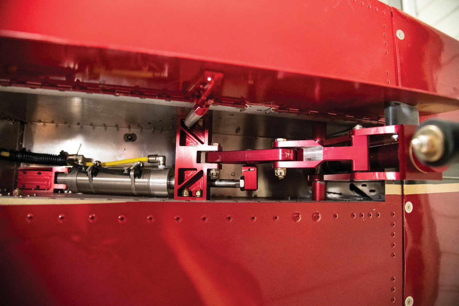
Probably the most important all-up testing you need to do is for the landing gear “up” and “down” indicators. There are two LEDs for each gear, and you adjust them by sliding the Hall effect switch for each one up and down on the pneumatic cylinder until it indicates in the right position. This is very easy to do in the “down” position as the cylinder is easy to see—but not quite the same when you have it retracted as the cylinders are hidden by the gear itself. Fortunately, it’s easy to simply remove the main gear trucks and just swing the upper gear leg to do this job. And once it is done, it should be good—at least until the next inspection.
The Final Touches
There are always a few things to do between when you think the airplane is finished and when it is ready to fly. Everyone knows about them, but nobody remembers them enough to build a list, and most builders tend to forget them between the last project and the current one. In the case of the little jet, we had a couple of weeks between the end of major construction and the beginning of the paint process, and while I figured this was time to work on something else, each day there was something to complete—or redo—on the SubSonex.

Fuel sender calibration is something you have to do when you get around to pouring fuel in the tank(s)—and a couple of things occur at this point. First, you figure out where the fuel system might be leaking. Be ready for little drips and messes. Wade in and fix them—that’s all there is to it. Then when you power up the fuel system and start pouring in calibrated amounts of fuel, you’ll find out if your gauging works or not. If it does, record the calibration data. If it doesn’t, be ready to drain, fix the problem, and start over. We had to do the latter on the jet when the capacitance sending unit turned out to be faulty. Oh yeah—we also had a drippy leak that had to be fixed!
Now is also the time to start fooling around with the EFIS and make sure that all of the sensors are properly connected and calibrated. Sometimes you have to get creative in order to test. For instance, how do you know that the OAT probe is working? How about an ice cube and a heat gun? (Not both at the same time, however.) We checked that and also had to find the channelization of things like the air pressure transducer for the gear pneumatics. Little things.
This was also a good time to just sit in the cockpit and start finalizing checklists. Although the factory manual has a checklist as a starting point, it is just that—a starting point. Every EFIS is different, every jet has a slightly different cockpit, and every pilot knows what is right for them—and I am no exception. So I printed out a draft and sat in the cockpit playing with procedures and flows, modifying the draft as I went. It took about four iterations before I was happy enough to be ready for flight…I think.
Finally, one of the big days we had been waiting for was the first engine start. Of course the engine had been run and trimmed on a test stand in Europe, so it wasn’t like we didn’t know it would run. But still…it was a pleasure to hear the turbine spin up and the burners ignite—proof that the airframe wiring and plumbing was sound!
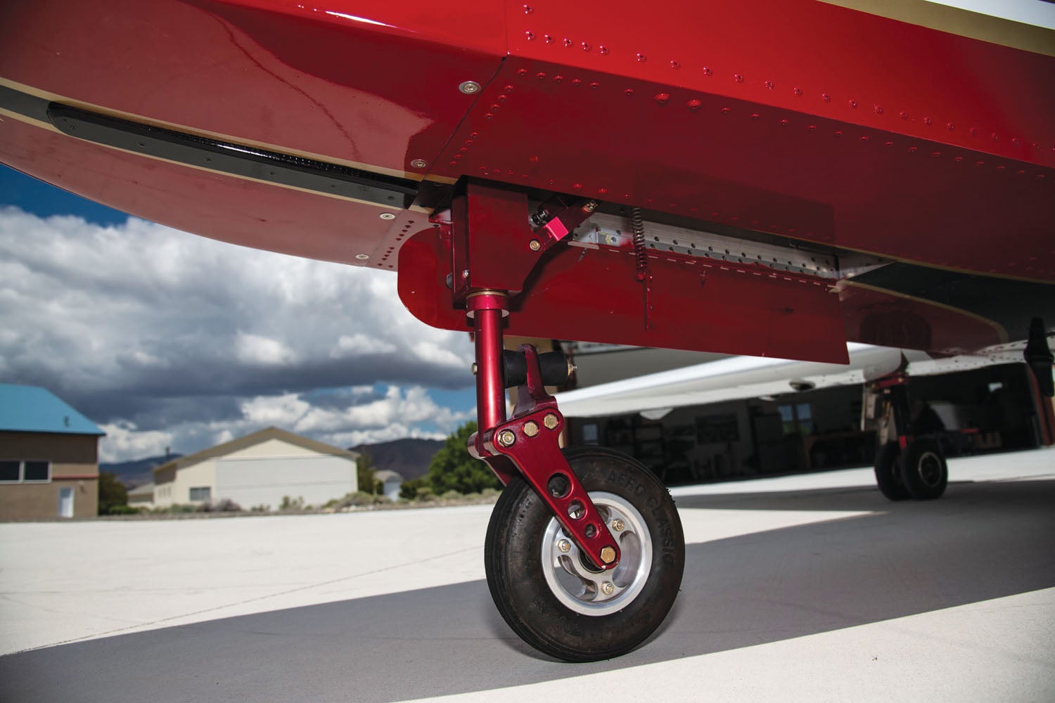
Taxiing the now-mobile airplane around our airpark was thrilling and fun—airport neighbors coming out to give a thumbs-up (then holding their hands over their ears). The jet proved to be docile on the ground, with plenty of power required to get it rolling, followed by a pull-back to slightly above idle to sustain a nice walking speed. For those raised on toe brakes, it takes just a little while to get comfortable with nosewheel steering and a hand brake—but if you take it slow, you get it quickly.
With taxi testing complete and all of the systems checked out, the airplane could be declared finished—or at least ready for the paint shop—which was next on the agenda.
Photos: Richard VanderMeulen and Paul Dye. Drawings: courtesy of Sonex Aircraft.
![[Credit: Sonex]](https://www.kitplanes.com/wp-content/uploads/2026/07/unnamed-6.jpg?w=218&h=150&crop=1 "Sonex Renames High Wing the Phoenix")


