When I bought my CH 701 kit from Zenith, one of my options was the Aeroflash nav/strobe kit with the double flash. The strobe flashes twice very quickly and then repeats every second. The kit comes with a power supply for each wing and works very well. Together the power supplies weigh close to 3 pounds, and each draws 2.7 amps. I have a Jabiru 2200 in my Zenith CH 701 with an alternator that only delivers 10 amps. With strobes, navigation lights, instrument lights, instruments, radio (in receive), etc., my total load is about 9 amps.
With the advent of very bright LEDs, I decided it was time for the CH 701 to lose some amps as well as a few pounds (its empty weight is 580 pounds). I found some 10-watt, 12-volt, 900-lumen, pure-white (6000 K) LEDs. Experimenting a bit, I determined that 15-millisecond flashes separated by 0.1 second were comparable to the original double flashes from the Aeroflash strobes on my CH 701. Not only that, but the LEDs seem to be just as bright with much less power required.
The 555 timer integrated circuit is reliable and easy to use. Two resistors (R1 and R2) and a capacitor (C1) are the main ingredients for an astable multivibrator; this is just a circuit that continuously delivers a positive pulse, then goes to zero for an “off” pulse, and then repeats. Along with C1, R1+R2 define the length of the “on” pulse while just R2 and C1 determine the length of the “off” pulse. The “on” pulse is always longer than the “off” pulse. Picking the right values for R2 can make the “off” pulse much shorter than the “on” pulse. We’ll see why this is important in a moment.
If we want 15 millisecond flashes separated by 0.1 second, we have to drive the LEDs with the “off” pulse and use the “on” pulse between flashes. This means we must invert the output of the 555, or make the “off” pulse go high and the “on” pulse go low. This just takes another transistor and a couple of resistors.
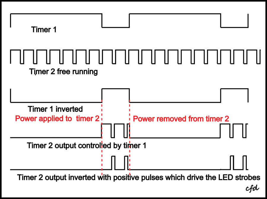
Now we have the LEDs flashing for 15 milliseconds every 0.1 second—close, but not exactly what we want. What we need are two LED flashes and then a waiting period of about 0.9 second before they flash again. Therefore, we need to power the flashing 555 long enough for only two flashes, then remove the power for 0.9 seconds, and repeat. Remembering that we have inverted the flashing 555 output, the first output is a low pulse of 0.1 second, then high for 15 milliseconds, then low for 0.1 second, and then high again for 15 milliseconds. All things considered, about 0.3 second of power is required every second. Thus, the double flash will repeat every second. What we need is another 555 timer (for power control) with an “on” pulse of 0.7 seconds and an “off” pulse of 0.3 seconds. Again, inverting this 555 output, we can now power the flashing 555 for 0.3 second every second.
Circuit Diagram Details
Since the power control circuit is electronically in front of the flash timer, my circuit diagram puts these components at the top and are numbered first. We will call the power control 555 “timer 1” and the flash 555 “timer 2.” Q1 inverts the output of timer 1. Q2 is an emitter follower, which means it follows the inverted output of Q1 but has enough oomph to power the timer 2 circuit. Q3 inverts the output of timer 2. Q4 is a power transistor emitter follower, which can drive the 1-amp LEDs. Note that Q4, driven by Q3, gets its power directly from the 12-volt source. Although the LEDs are 10 watts, their duty cycle is about 5% and thus do not need a heat sink. Nor does Q4 need a heat sink. All of the resistors are 1/4 watt; the capacitors should be 40 volts or higher; Q1, Q2, and Q3 are 2N2222; Q4 is a TPI-120, which can handle 5 amps; and the D1s are 10-watt, 12-volt, 900-lumen, pure-white (6000K) LEDs. When installing the capacitors, be sure to honor their polarity (minus to ground). Most components are readily available, however, I found Q4 and D1 at banggood.com.
Making the LED Mounting Wedge
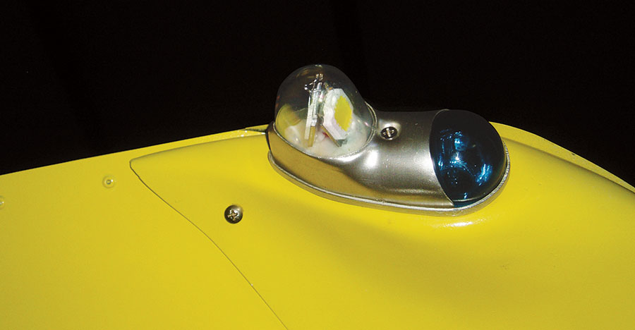
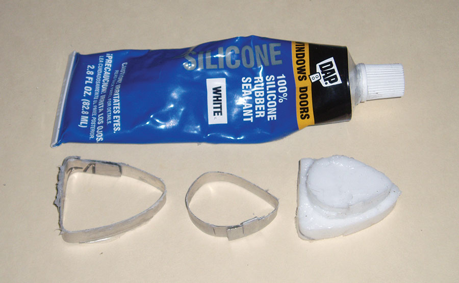
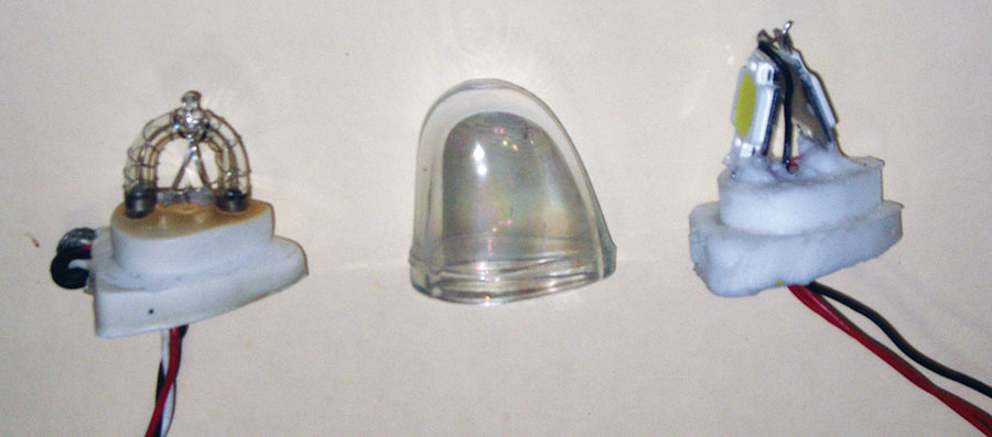
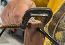
The Aeroflash xenon flash tube is mounted in a silicone wedge that fits snuggly inside the clear lens and aluminum base. The next step will be to fabricate an equivalent wedge for holding the LEDs. A couple of molds and a tube of silicone will work just fine. Start with the large mold and give the silicone a day or two to cure throughout and then add the second layer.
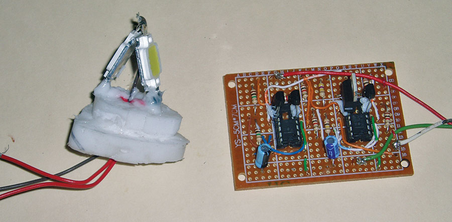
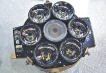
The LEDs are positioned back-to-back with the minus terminals at the top; these are connected together with a black wire. Each LED’s positive side is connected to a red wire. The LEDs are mounted on the silicone wedge, with the wires going through the wedge. Dabs of silicone at the base of the LEDs will hold them in place for insertion into the clear lens. Dabs of silicone will also anchor the transistors. For the Aeroflash red and green navigation lights, a ground wire is required.
To view the LED strobe in action on my Zenith CH 701, download the video file from Dropbox.
Although, I describe how to modify the Aeroflash unit for LEDs, the LED strobe can be implemented with any clear lens and lamp base.





The Q4 transistor, should not it read TIP120 by chance? Seems I cannot find any transistor marked TPI12).
Thanks.
Correction:
The Q4 transistor, should not it read TIP120 by chance?
Seems I cannot find any transistor marked TPI120.
Thanks, George
Yes, here is link.
https://www.banggood.com/10pcs-TIP120-NPN-TO-220-Darlington-Transistors-p-932779.html?rmmds=myorder&cur_warehouse=CN
Thanks for clarification Chuck!
Also, I assume your capacity ‘mfd’ actually meant to be µF = microFarad, right?
Perhaps millifarad would be way too big capacity and the cap would be much larger too.
(Normally ‘m’ stands for milli, ‘M’ for Mega and ‘µ’ for micro, ‘k’ for kilo, abbreviation ‘K’ for Kelvin, abbreviation for Farad unit is ‘F’.
I know many people do not adhere to the standard notation convention, which leads to unnecessary confusion.)
Thanks again for nice project.
Hi Chuck, thanks for sharing your great idea. I’ve temporarily assembled one and it works great. I’ve also designed a 3D printable mold for the LED base, soldering fixture to properly distance the LEDs. I also designed a mold to replace my rear half sphere light with LEDs. I have made a circuit drawing to make a 7x9cm PCB and a housing to accommodate the PCB. If it is OK with you I could post them on Thingiverse for other people to use.
Thanks again,
Paul
Hello Paul,
that’s a great news!
I just received today the last component I needed, planning to play with it on weekend.
I hope Chuck agrees to your proposal, I’d love to have access to your contribution. This is a beauty of open source creativity.
Chuck if fine with it, now I’m waiting for a reply from Kitplanes.
Here it is. PCB drawings will be added once printed, assembled and verified.
https://www.thingiverse.com/thing:3870696
Paul, That’s great & thanks. What size PCB/breadboard would I order?
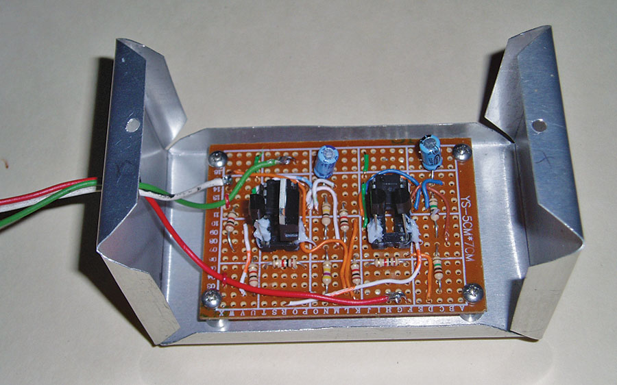
5x7cm would do. There is also a spot on the PCB for connecting a navigation light power wire. It basically just go through the box so all the wires from the light would connect to the same connector on the PCB housing.
Also I’ve made and fitted 3 of these LED bulbs into the lens. The light is better distributed (seen from top or bottom).
The files for 3D printing (mould for the silicon plug and wiring mockup plug) will be uploaded soon.
Files uploaded.
Great article. Are there any FAA regs for front lights? I’ve want to build by own cause all certified led lights are so expensive.
I found this, but it may be out of date. https://www.faa.gov/documentLibrary/media/Advisory_Circular/AC_20-30B.pdf
Hi Chuck,
I’m having nightmare time with the PCB. I’ve put it on side for a while and now back on it but I cannot make it right. I’ve tried 3 different layouts but there is no output. Can you take a look at the picture – https://ibb.co/vq6Rh5C – and let me know if you see something wrong or if there is something else?
Thanks a lot,
Paul
The PCB layout is OK. After several email exchanges with Paul, he has it working.
Can I buy or order some of the printed circuit boards from anyone or any company that has already made them. Might be interested in 12 of them, if the price is right.
I’ve designed the layout of printed board – files are ready for download here in rar file – https://www.thingiverse.com/thing:3870696.
I made a few but just for myself. They’re good and tested but not a professional quality that I’d like to sell to anybody. I’m sure you can find an online service that can make these boards for you when you provide your art. Let me know if you need a different files (on the site, they are jpeg but I can provide you with vector files).
Hi Paul, would you be able to create a version of the supply in a single flash version?
Chuck, I have been planning to do this LED project with my CH 801. I am curious, what is the brightest led that is sold that I can use? I have looked at using a CREE 3590 or XHP50 and making my own housing to accommodate the size. If I am going to build it, go big or go home right?
My question is this: Other than the CREE single-die chips which I mentioned, do you think an LED array choice vs a single-die chip would be better for my purposes? I plan to use them as strobing anti-collision lights and as landing lights.
I can accommodate the amps, so why not up the lumens?
I went for the professional PCB fabricating service and might have some extra PCBs, if anyone is interested. Sometime in the next 2 or 3 weeks. I might even try to design another version with SMD components.
If I made the connections correctly, this circuit doesn’t seem to work very well. I tried this on Proteus, but it doesn’t work. Please send me an e-mail.
I ran this circuit and it works without any problems. What you need to pay attention to is the capacitor values, namely (.47mfd & .22mfd), the values should be 0.47uF and 0.22uF. If friends who can’t get it to work write to me, I will help. Thank you, good job
I guess I am from the old school where mfd = microfarad.
I never heard of a milli farad.