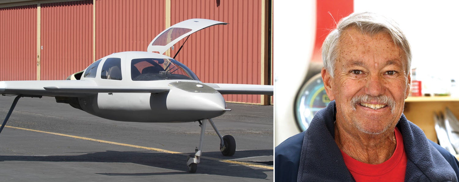
Across from my hangar is Kevin King, the proud owner of a Glassic Composites SQ2000. If you’ve never seen one, don’t feel bad. They only sold a handful of kits, and after at least two changes of ownership by the mid-2000s, had pretty much disappeared.
When Kevin purchased the airplane from the widow of the builder in 2018, it was airworthy and flying, but needed some cosmetic work. Like many builders, this one did not install the wheel pants. Builders often choose to keep the landing gear, brakes and tires naked during the 40-hour Phase I testing to facilitate the inspection regime that goes with breaking in a new plane. Others leave off the wheel pants simply because they are anxious to start—and keep—flying. Whatever the reason, the wheel pants were never installed on Kevin’s SQ2000. As he racked up hours on the plane (including a Florida to California cross-county trip), it became clear that not having wheel pants was holding back the cruising speed.
After so many months of staring at the wheel pants and researching how to best mount them, including going to the Rutan Reunion in 2019 and talking to every canard-type owner he could find, Kevin was still unsure.
All the while, I was having fun with old Kev. Back in 2014, when I bought my Jabiru, the circumstances were nearly identical. Like Kevin, I purchased my Jabiru from the widow of the builder and the wheel pants had never been installed (see “To Launch a Light Sport—Redux,” May 2015). Not a week went by that Kevin or his hangar mate, Donnie Eubank, wouldn’t ask, “I wonder how that Jabiru would look with wheel pants?”
I eventually got tired of hearing it and got around to mounting the wheel pants. As you might guess, I regretted not having done it sooner. My cruise speed increased from 112 to 117 knots!
So when Kevin bought the SQ, it was my turn: “Hey Kevin, I sure would like to see how the SQ looks with wheel pants,” to which I added, “I bet you’re losing 10, 15 or even 20 knots with those naked wheels.”
Then, when word got out that AirVenture was on for the end of July 2021, we started talking plans to fly the SQ to Oshkosh. But I told Kevin, “We have to put the wheel pants on first.”
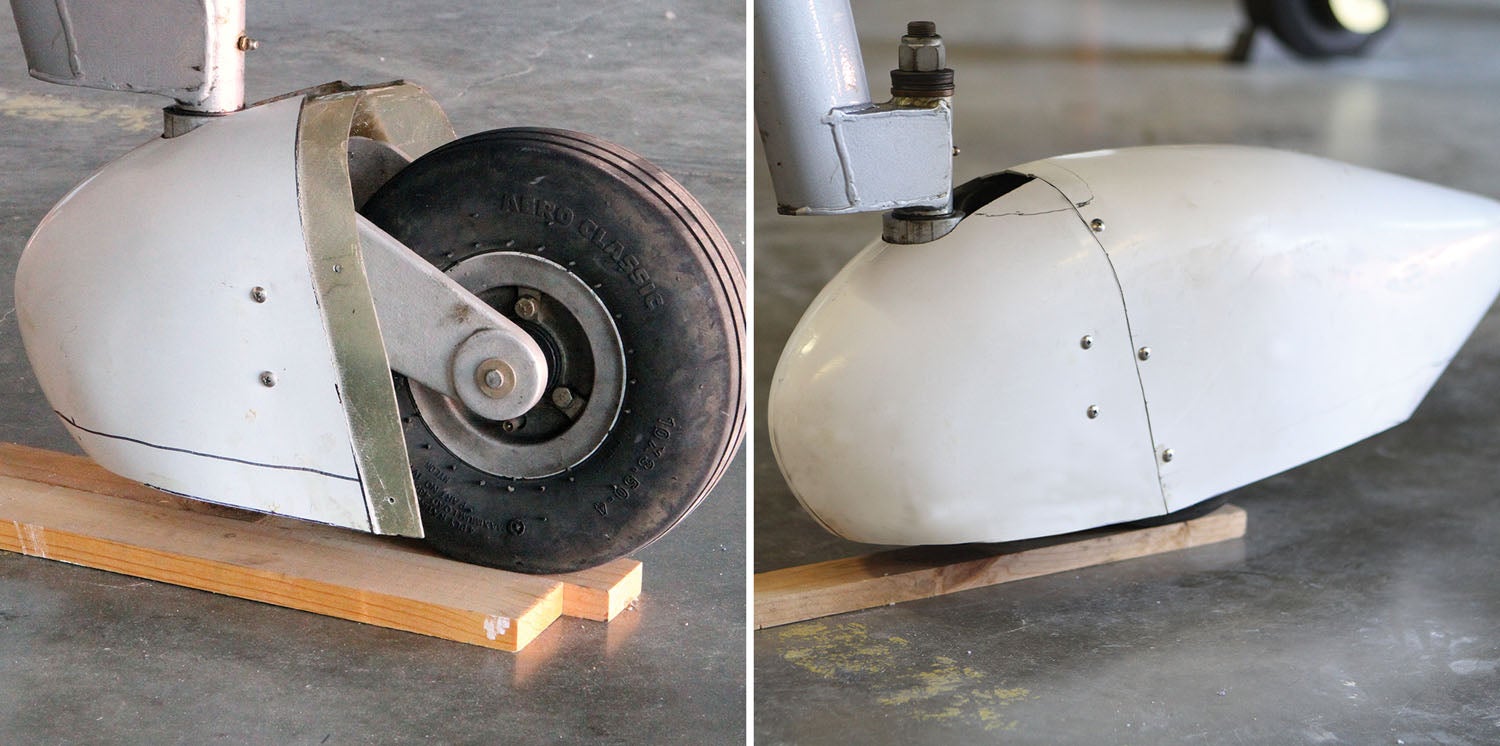
After some discussion, we agreed the wheel pants he got when he bought the plane (generic catalog items called “gel-coated fiberglass wheel pants”) probably wouldn’t work for the mains, but might work for the nose gear. The challenge was where to mount it, and how.
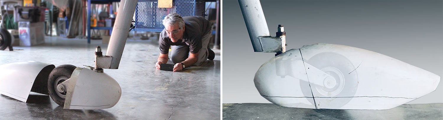
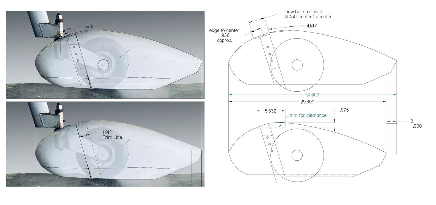
I remembered a while back a “see-through” composite Photoshop image created by a builder to visualize the relationship between the engine and his custom cowling. This seemed like an extremely useful technique to “fit up” curvy parts with other curvy parts that otherwise have no physical plane or straight face to take reference measurements. So, borrowing that idea, I used my smartphone to take side-view photos of both the nose gear and the wheel pant. Back home, I opened the images using Photoshop and combined them using the “layers” feature.
Once an image or a part of an image is a layer, you can control the level of transparency and “float” it over the background to position it wherever you want. After a few minutes of experimenting, I had the wheel pant positioned more or less in the right spot.
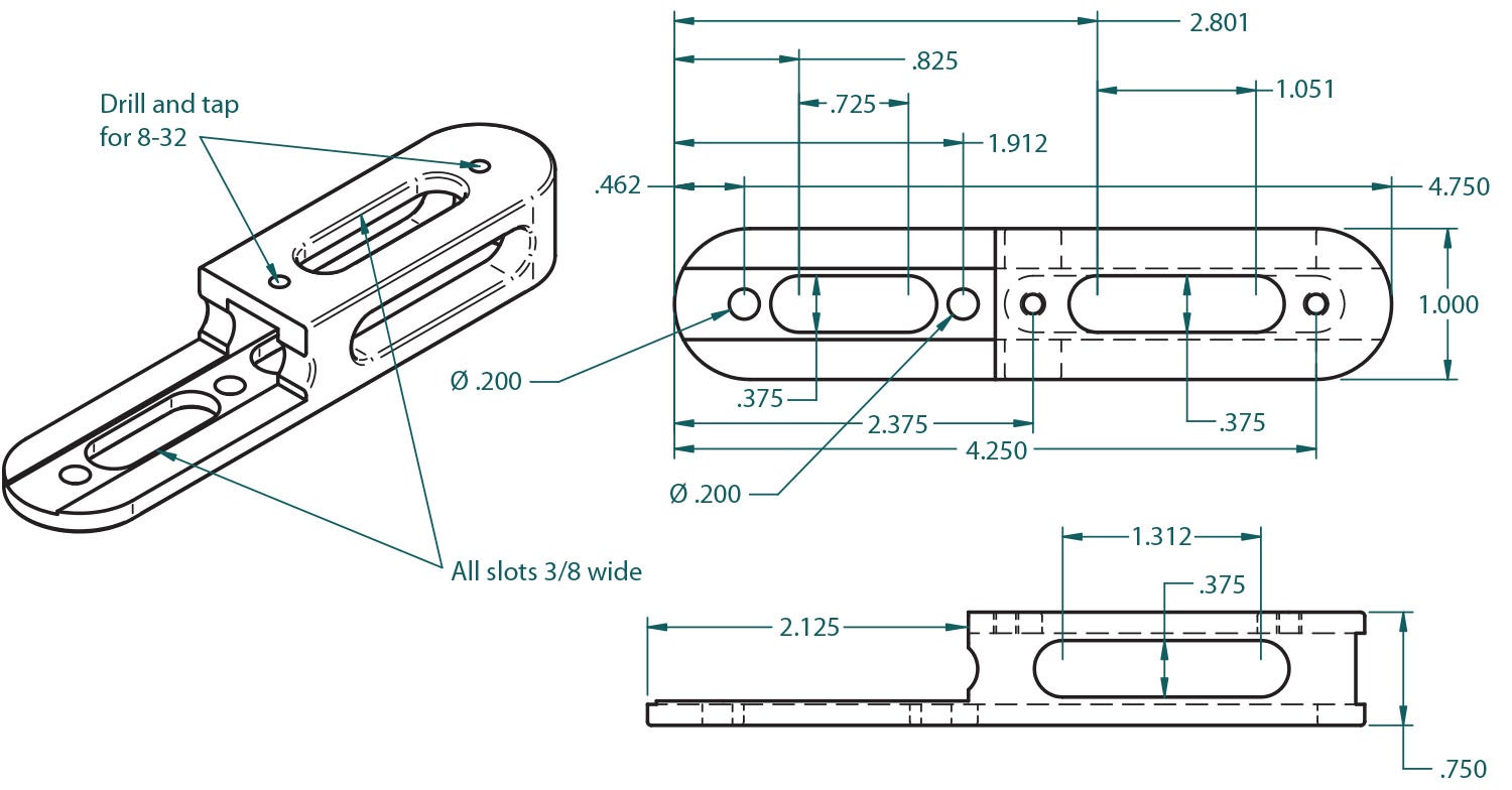
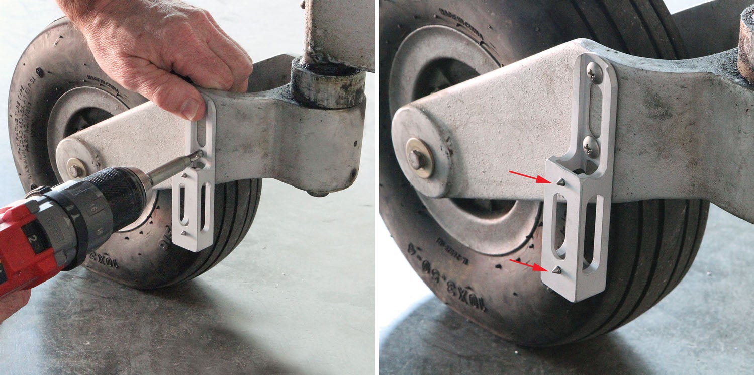
I saved the resulting composite image as a JPEG image and loaded it into my CAD software (Solid Edge). By scaling the photo, I was able to make a dimensionally accurate 2D view. This allowed me to get a more precise idea where and how the front half of the wheel pant could be attached to the fork. With the composite imagery in hand and dimensional estimates from the CAD program, I sketched out a bracket to bolt to the fork and provide the correct spacing and support for the wheel pant.
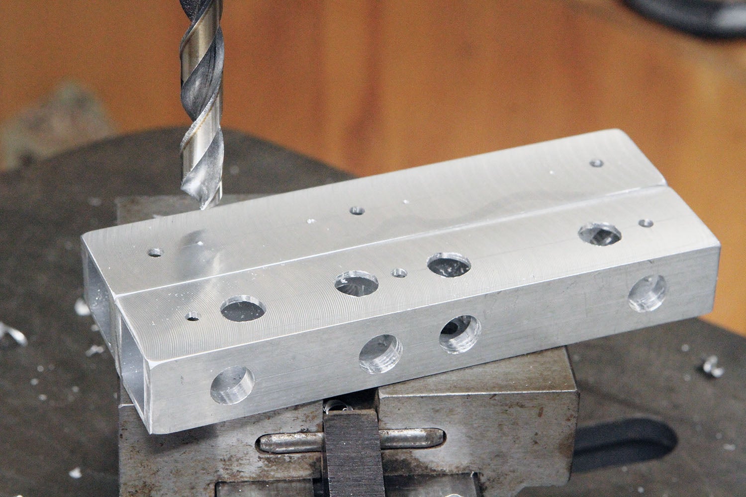
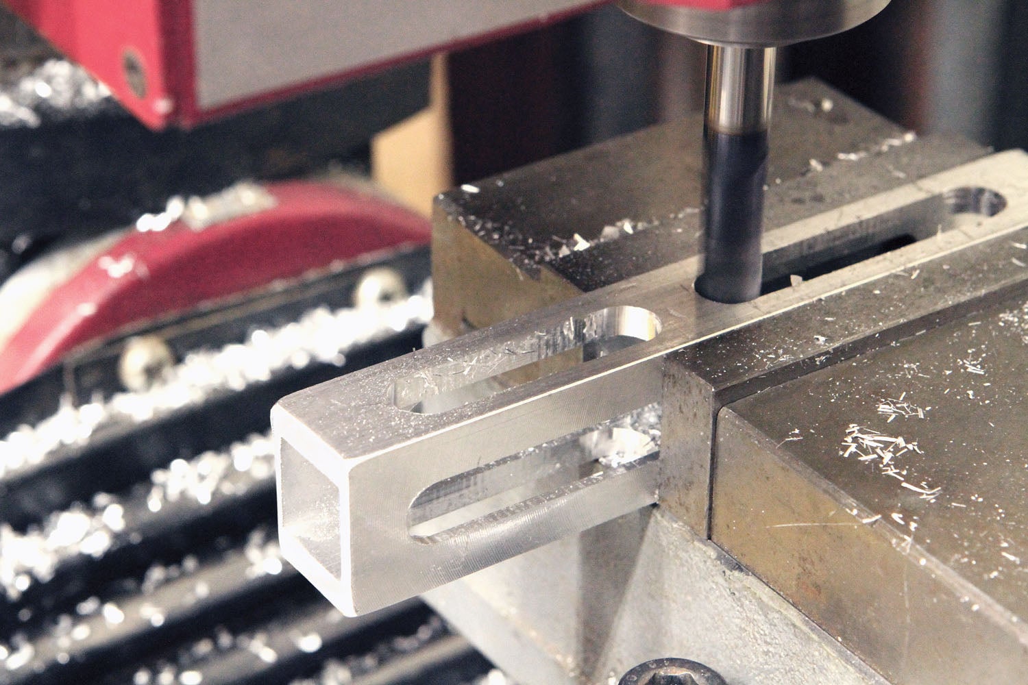
To save weight, I selected thick-wall 1-inch aluminum square tubing. A box section makes for a strong and lightweight structure, which I made even lighter by milling slots between the mounting holes (refer to the sketch).
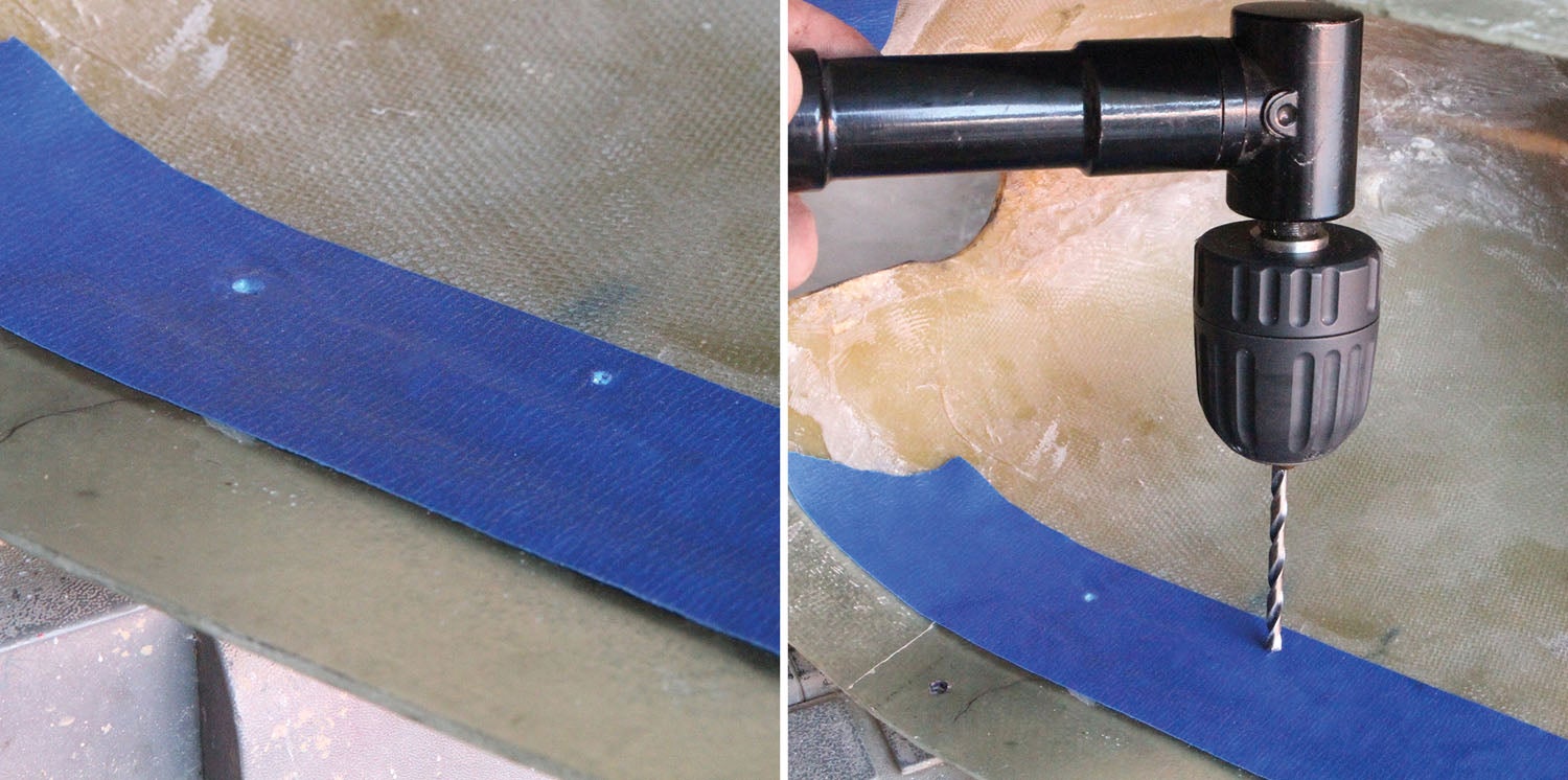
Please note the 8-32 threaded holes in the bracket. These were eventually drilled out in favor of floating nut plates for the actual fixing of the wheel pant to the bracket. But they served a useful purpose for marking the holes to be drilled in the wheel pant. I took two 8-32×1/2-inch cap screws and ground a sharp point on the end of the threads. When threaded into the brackets, these served as locating punches for marking where to drill the wheel pants.


In the homebuilt world, it is fairly well accepted that any individual modification made to the airframe is worth “about 4 to 5 knots.”
And the sum total of all modifications made will add up to “about 4 to 5 knots.”
I’m a bit skeptical that a set of wheel pants would be worth anything like 20+ knots.
Probably more like “about 4 to 5 knots.” 😉
I bet he was just giving Ken incentive to add wheel pants. And, depending on how slick the rest of the plane is, they might add more than 4 to 5 notes
Knots!
Tip: I found a MUCH simpler, and IMO better GUI in a photo editing software (and open source): Paint.net available (free): http://www.getpaint.net
Comments are closed.