When they made my C-182A in 1957, they put two com antennas side by side on the top of the fuselage. The antennas met, fell in love and got married. The wedding was OK, but the reception was great (ahem).
First of all, let me clear up a misconception. I used the term VSWR—voltage standing wave ratio—and was asked the difference between SWR and VSWR. There is no difference. The only kind of standing wave (SW) you can have that is easily detectible is a voltage standing wave, and the ratio of the power going out from the aircraft transmitter and the power/voltage reflected back down the transmission line from a mismatched antenna is the “R.” SWR and VSWR are exactly the same thing.
So why should we care about VSWR? A couple of reasons. First, you are paying for transmitter watts in your airplane radio in Franklin$, and that is just tossing some of it away with a mismatch between transmitter and antenna. Second of all, that reflected power is coming back down the line and heating up your expensive output transistors, which increases their failure rate. Third, some of that power coming back down the line is being reradiated behind the instrument panel and can affect some of the other radios and instruments in the airplane.
Before we get too deeply into this subject (and yes, there will be math today) let me state that any power source, be it a battery or a transmitter, has some sort of “characteristic impedance” associated with it. Let’s take a 12-volt storage battery as an example. Inside that battery, we have acid and metal plates. The metal plates, no matter how big, have some resistance—all metals have some resistance and lead-plate batteries are no exception. That resistance may be very low (a few milliohms) but it is still real, and that limits the amount of power the battery can put out. We can characterize this battery with a pure voltage source in series with the plate resistance. Any source of power can be characterized with a pure power source in series with its internal resistance.
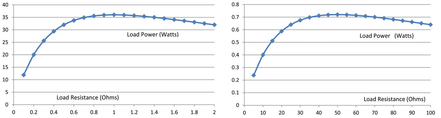
Not intuitively (at least for me early on), it seemed that the more current I could get out of the battery, the more power I would have for my load. But graphs are a wonderful thing. Let me take a couple of examples. Let’s say I have a 12-volt (a purely arbitrary number) power source with an internal impedance (a purely arbitrary number) of 1 ohm (1 Ω). What load can I use to get maximum power out of this battery? Let’s start with a 0.1Ω load and just keep on increasing the resistance to see if there is some point that gives me maximum power to the load. We start low and then increase the load resistance up. Where does the maximum power in the load peak? Strangely enough, at 1Ω. Maybe I fudged the numbers. Let’s try 50Ω. Maximum power is at a load of 50Ω. Pick any voltage and any internal resistance you like, and maximum power will be where the load is equal to the internal resistance.
What does this mean for us? It seems that the clever RF engineer who designed your radio took the fairly low resistive part of the transmitter transistor output through a fairly lossless capacitor-coil (inductor) combination transformer up to 50Ω output. This means that the couple of ohms of true output resistance is the only lossy item, and that most all of the power will be consumed and radiated at the 50Ω antenna port. Clever, those RF guys. And you get maximum power into the antenna where the 50Ω radio matches to the 50Ω antenna.
Here comes the math. Not to worry yet how we measure the VSWR, but presume that we do. The percent power that is reflected by an antenna is given by the equation:
% reflected= ((r-1) / (r + 1))²
…where r is the measured VSWR. Let’s see what that means. How about the minimum VSWR we can expect from a dipole or a whip antenna into a 50-ohm system, 1.5:1. r = 1.5. 1.5 – 1 = 0.5; 1.5 + 1 = 2.5. So, 0.5/2.5 = 0.2. 0.2² = 0.04, or 4%. So, your 8 watt transmitter is delivering 7.7 watts to the antenna and losing 0.3 watts in reflected power. Not bad.
Now let’s take the antenna to the band edges, where our good 1.5 VSWR at the band center is now a 3:1 VSWR at the upper and lower band edges. Same formula, but now your reflected power is 2 watts and your transmitted power has dropped to 6 watts. Not so good, especially since that 2 watts reflected power is still really heating up that expensive output transistor that is prone to suddenly departing the circuit after too much heat. And things only get worse from there.
So we’ve figured out that high VSWR is bad. What can we do about it? With store-bought antennas, not much. And with receive antennas, all it does is cut down your range. You can take what you can get. It is only for transmit antennas that we really worry about VSWR.
So far as I know after a 60-year study and design of antennas, there is only one thing that can get you more bandwidth at the edges of the band, and that is a fatter antenna. No skinny wires, just wide copper strips.
OK, enough about the effects. How do we measure what we have in our aircraft and what does it take to do the measurement.
VSWR is a two-part measurement…How much do we have coming down the line and how much is bounced back? There are two main ways to measure this, and they should come to the same number, no matter how you do it.
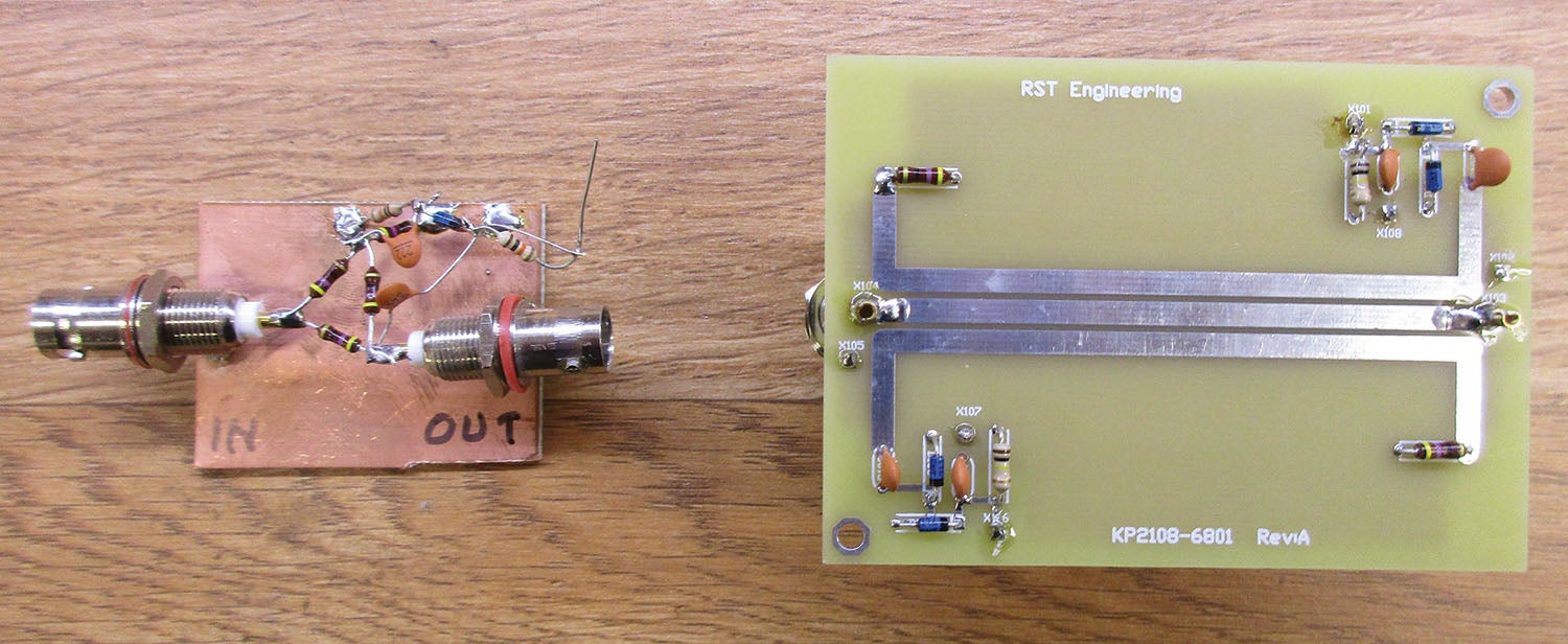
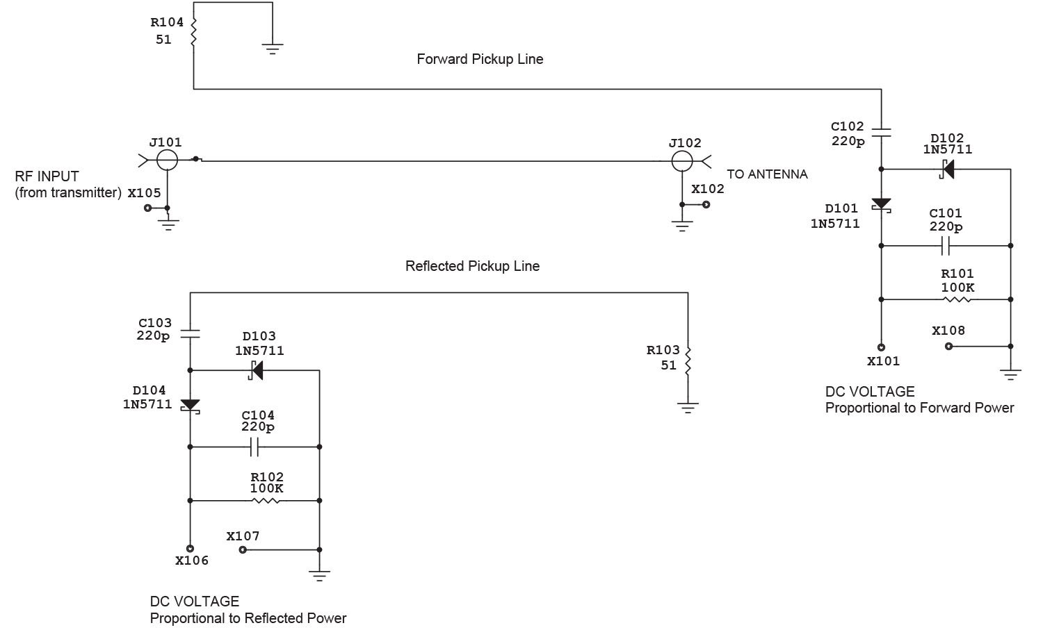
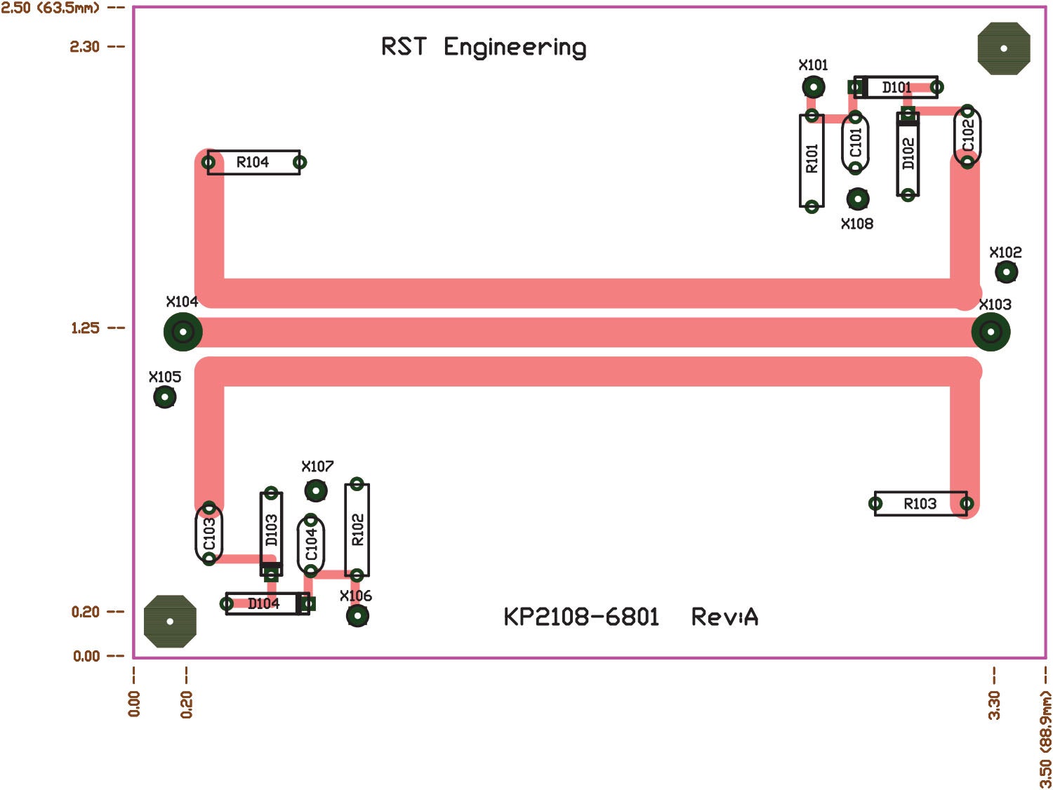
One is the “reflectometer” method. You send a transmit power down a calibrated microstrip line with two calibrated lines to either side of it. One of the lines measures the forward power (or the voltage corresponding to the power injected into the line by the transmitter) and a parallel line measures how much of that power is reflected down the line by the antenna. Power forward divided by power reflected gives you a measure of VSWR.
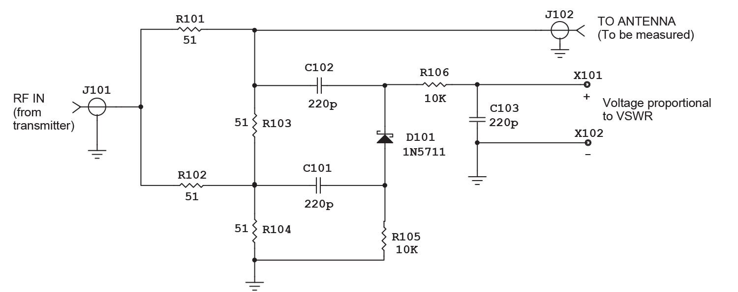
The other way is the Wheatstone bridge method. Wheatstone bridges consist of four “resistors.” Two of them are for balance, one is for standard, and the fourth is the variable to measure against the standard. Again, the bridge gives you the power transmitted and the power reflected, which is the measure of VSWR.
Me? I’m happy either way, but I will point out that the reflectometer requires some PC board “microstrip” work to make the measurement, and the Wheatstone bridge requires plain old resistors. The upside is that the reflectometer can be done with quarter-watt resistors, and the Wheatstone requires resistors capable of handling all the power that your signal generator can provide.
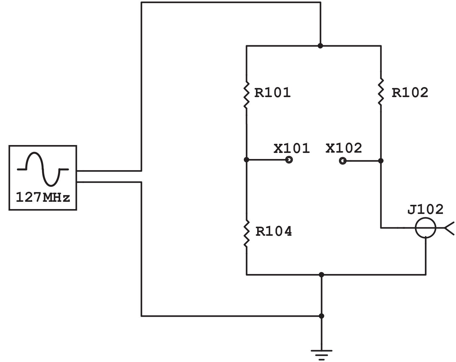
Oh, the signal generator? You’ve probably got one. It is called a handheld portable, capable of testing the antenna at the center and edges of the band. With a watt of power or so, you are working with volts of signal, more than enough to use a Harbor Freight $8 digital voltmeter as your measuring device.

As I write this the first week of April, it seems that winter has broken its back. Up here in the Sierra at 3000 feet msl, we are at 75–80° F during the day, and the apples and people are blossoming out. That means with any kind of luck at all, I can get back to doing more work on the HOG (Hangar Off Grid) project for the next six months.
Until then, stay tuned…


The problem with being too fussy about SWR (I am an old bloke) is that if you sweep across the whole of the Airband, the SWR of your lovely quarter wavelength might be 1:1 at the middle say 125 MHz, but could be much different at 120 or 130. That is just the nature of the beast.
The center of the air band (geometric as well as arithmetic) is 127 MHz. All you can do is cut it for band center and if the VSWR at the band edges are outside of your required limits is to make the antenna out of “fatter” elements. To a first approximation, 1/2 inch copper tape is every bit as good as 1/2 inch diameter solid wire.
THanks,
Jim
A vertical element antenna, one quarter wavelength long, has an impedance of 32 Ohms. It is very close to 50 Ohms, and is what aircraft antennas have been for as long as radios have been put in aircraft, until the feds added more channels.
When the extra channels were added, the antenna manufacturers created the broadband antenna. As an added bonus, the SWR went down for these antennas as well! By making the element longer, it increases the impedance to 50 Ohms, and they use a capacitor to offset the added inductance.
This form of broad banding an antenna has been used for a very long time in aircraft and other areas where antennas are used.
Unfortunately, aircraft antennas of this type, usually get put into a fiberglass shell that gets a blast of expanding foam to support the parts. And such antennas last quite a long time, usually, unless moisture gets inside the works.
If you look at any aircraft that has the antenna inside a radome of fiberglass, you will see many of the fiberglass shells are eroded and are perforated to where moisture can penetrate, especially at flying speeds. And any moisture inside the shell will detune the element, especially if the moisture has been inside long enough to corrode the metals used for the antenna!
Unfortunately, an antenna that is damaged internally isn’t always going to have a bad SWR. But one way of checking for damage, is to tune in ATIS and fly away fro the airport till the signal starts getting scratchy. You should be able to get 100 miles from the airport before this happens. You can also find if there are any RF shadows at this distance as well, by flying in a flat circle and seeing if the ATIS signal disappears.
Comments are closed.