It’s easy to think of a propeller blade as a wing flying around in a circle, but in real life, propeller blade aerodynamics are more complicated than wing aerodynamics because the flow conditions vary dramatically over the span of the blade.
On a wing, every element along the span sees the same oncoming air flow. This is not true for propeller blades. The prop is spinning around its shaft, while also moving though the air. The flow conditions at any point along the blades are the result of the combination of the velocity due to the spin of the propeller and the velocity due to the forward motion of the airplane. These cause large variations of both airspeed and inflow angle over the length of the blade.
A properly designed propeller needs to take both of these effects into account. Last month, we looked at the effect of the variation of airspeed and Mach number along the blades. This month, we turn our attention to the apparent incident angle of the oncoming air each blade element sees, and why propeller blades are twisted.
Blade Inflow Angle
As the propeller moves through the air, each point on the blade follows a helical path. The angle of this helix is determined by the rotational speed of the propeller, the forward airspeed, and the radial distance from the axis of rotation. The angle is different at every radial station on the blade.
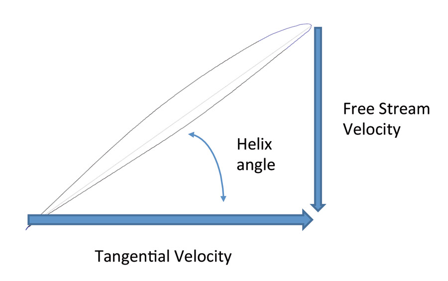
Figure 1: The helix angle at each point on the blade is determined by the tangential velocity due to prop rotation and the free stream velocity (airspeed) of the airplane.
Figure 1 shows how the local helix angle is determined. The blade element has a tangential velocity (velocity due to propeller rotation), which is normal to the propeller axis of rotation. The forward airspeed of the airplane produces a velocity component that is parallel to the propeller shaft. The local helix angle is determined by the relative magnitude of the axial velocity (due to airspeed) and the tangential velocity (due to rotation). The propeller blade element sees an incoming airflow approaching at the local helix angle. Note that the lift generated by the propeller blade element is normal to the incoming flow, rather than parallel to the propeller axis of rotation. The helix angle is always 90 degrees at the center of the prop hub, where the tangential velocity is zero. As we move outboard on the blade, the angle decreases.
The Advance Ratio
The helix angle described by any point on the blade is determined by the ratio of the tangential velocity and the airspeed. This is independent of the absolute value of these two speeds. As long as the ratio is the same, the angle is the same. Because of this, engineers have defined a quantity called the “advance ratio” of a propeller, which is used in calculations of propeller characteristics. It is also a fundamental parameter against which experimental propeller performance data are plotted. For reasons undoubtedly long lost in history, the symbol for the advance ratio is a capital “J.”
The advance ratio (J) is given by:
J = V/(nD)
Where:
V is the airspeed in feet per second
D is the propeller diameter in feet
n is the propeller rotation rate in revolutions per second
As its name implies, the advance ratio is proportional to the ratio between the tangential speed of the propeller blade tip and the forward speed of the airplane. For a given propeller diameter and rotation rate, the advance ratio is proportional to the airspeed. Figure 2 shows the value of advance ratio for a 6-foot (72-inch) diameter propeller as a function of airspeed for two values of rpm. Note that for the low airspeeds typical of ultralights (50 knots) the advance ratio is less that 0.5, while for fast airplanes it is typically 1.0 or above.
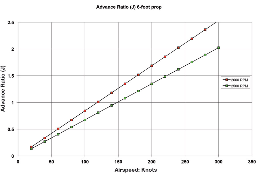
Figure 2: Advance ratio (J) for a 6-foot prop.
Inflow Angle and Blade Twist
One reason advance ratio is an important consideration when designing or selecting a propeller is that both the magnitude and the distribution of inflow angles along the blade change with advance ratio. Figure 3 shows the local helix angles over the blade plotted for a range of advance ratios.
The first thing we note looking at the curves is that as advance ratio increases, the whole curve moves up, indicating a steeper helix angle for the propeller. This is not surprising. What it is telling us is that as airspeed increases (higher advance ratio), we need a higher-pitch propeller.
The curves also illustrate a second, more subtle phenomenon. For a propeller to operate efficiently, it is desirable to have the majority of the blade at the same angle of attack relative to the local incident airflow. This causes most of the blade to be operating at the same lift coefficient. Ideally, the whole blade is operating at the lift coefficient at which the blade airfoil achieves its maximum lift-to-drag ratio. We achieve this uniform angle of attack distribution by twisting the propeller blades properly.
Look at the bottom curve, which is for a very low advance ratio. Notice that although the inflow angle is very high at the root, it falls off very rapidly, and by 20% of the radius, it is down to just under 10 degrees. Over the remaining 80% of the blade length, the inflow angle drops to about 2 degrees. If we wanted to keep all of the sections on the blade of this propeller at the same angle of attack relative to the local incident airflow, the blade would need about 8 degrees of twist from the 20% radial station outboard.
Inboard of 20% we would need a lot of twist, and the blade should theoretically have an incidence of 90 degrees at the root. Fortunately, the inner 10% to 20% of a propeller blade is usually either part of the hub or inside the spinner.
Now let’s turn our attention to the top curve on Figure 3. This curve is for a propeller operating at a much higher advance ratio than the previous example. At 20% of radius out from the center, the local flow angle is about 70 degrees. At the tip, it has dropped to about 28 degrees. To achieve uniform blade-element angle of attack, this prop would need about 42 degrees of twist between the 20% radius station and the tip. This is quite a difference from the 8 degrees needed for the very low advance ratio prop.
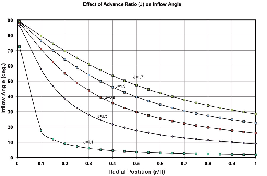
Figure 3: Effect of advance ratio (J) on inflow angle.
Figure 4 shows the twist required to achieve uniform blade angle of attack as a function of advance ratio. If we compare an ultralight-like value of 0.3 for “J” to the 1.0 to 1.5 typical of faster airplanes, we can see that there is a dramatic difference in the twist distribution required for an efficient propeller. If the twist in the propeller blades does not match the advance ratio at which it is flying, part of the blade will be at a non-optimum angle of attack.

Figure 4: Effect of advance ratio on propeller blade twist.
Consider a ground-adjustable or controllable-pitch propeller designed to fly at low speed (low advance ratio). Suppose we decided to use this propeller on an airplane that flies faster than the design speed of the prop. To get thrust out of the propeller, we add pitch by rotating the whole blades. The blades are twisted for low speeds and do not have enough twist for high speeds. After the pitch change, the tips will have too high an angle of attack, and the roots will be at too low an angle of attack.
This situation is very inefficient for two reasons. The inner portions of the blades might actually be operating at negative angle of attack, producing negative thrust at high speed. Even if they are not, they are not producing their share of thrust. They are still producing drag that opposes the rotation of the propeller and soaks up engine power without doing anything useful. During early flight tests on my Facetmobile, I was using a propeller designed for ultralights. It pulled very well during the takeoff roll and initial climb, but cruise performance was disappointing. After a few flights, I noticed that I was getting bug strikes on the forward face of the inner third of the propeller blades. Obviously, this was not an efficient situation.
This does not mean that the propeller was a bad design. It was designed to produce a lot of thrust at low airspeed. It did this well. Unfortunately for me, it was not well suited to the higher-than-ultralight cruise speed of the Facetmobile.
At the other end of the blade, the tips are too highly loaded, and are operating at a lift coefficient that is higher than the best L/D lift coefficient of the blade airfoil. Once again, too much blade drag is being paid for too little thrust.
One important lesson comes from this. It is common for propeller manufacturers, particularly those who sell to the ultralight community, to advertise how much static thrust their prop produces. A static propeller is at the lowest of advance ratios: zero. Static thrust might be a valid figure of merit for propellers for very slow flying airplanes, but it is essentially meaningless as a measure of how good the prop will be on a faster-flying machine.
If the situation is reversed, and the blade is twisted for higher advance ratio, but de-pitched and flown slowly, once again we find some inefficiency. The inner portion of the blade is at too high an angle of attack, and the tip is at a lower-than optimum angle of attack. The loss of efficiency is less severe than the case we just discussed. The outer portion of the blade will be closer to its optimum angle of attack, and while the inner portion of the blade is operating at too high an angle of attack, it is at least producing thrust. For a variable-pitch propeller, it is much better to twist the blade for optimum performance at cruise and accept the loss of efficiency at low speed, than to fail to put sufficient twist in the blades.


