To stay at a constant safe operating temperature, the engine of an airplane must reject excess heat to the surrounding air.
To properly cool the engine, air must flow into the engine compartment from outside the airplane, absorb waste heat from the engine and then flow overboard to carry the heat away.
In previous editions of “Wind Tunnel” we have followed the cooling air through the inlets, into the upper plenum, over the cooling fins on the engine’s cylinders and into the lower plenum. Once the air enters the lower plenum it must leave the airplane and return to the outer airflow, carrying the heat it absorbed from the engine with it.
We now turn our attention to the lower plenum and the outlets through which the cooling air leaves the airplane. The entire cooling airflow path should be designed with two fundamental goals in mind.
The first and most important goal is to ensure there is enough cooling air flowing over the hot parts of the engine to cool it properly.
The second is to minimize the drag penalty caused by the cooling airflow. This includes the lower plenum and outlets.
Cooling Airflow
Airflows are driven by differences in air pressure. Air flows from areas of higher pressure to areas of lower pressure.
The cooling air is driven through the cooling fins by the pressure differential between the upper and lower plenums. It’s essential for the air pressure in the lower plenum to be lower than the pressure in the upper plenum to provide a pressure differential to drive the cooling air through the fins on the cylinders.
The pressure recovery of the inlets drives the pressure in the upper plenum. The air pressure at the outlet face drives the pressure in the lower plenum. There must be enough difference between the two to drive the cooling airflow through the system.
Leaks
In our discussion of internal flow in the upper plenum, we saw the importance of sealing the plenum so that all of the air pressure recovered by the inlets is retained, and all of the air that enters the cowling must flow over the hot parts of the engine rather than escaping through leaks in the cowling or baffles. There should be no air leak paths between the upper and lower plenums that would allow air to flow through without cooling the engine.
Its equally important that the lower plenum itself be sealed well enough to isolate it from the outer airflow except at the outlet itself and to ensure that no air leaks between the upper and lower plenums without flowing through the cooling fins on the cylinders. There are two reasons for this.
The first is to ensure that the air pressure in the lower plenum is as low as possible to maximize the pressure differential between the upper and lower plenums.
The second is to minimize drag. The cooling air should leave the airplane by flowing out of a properly shaped and directed outlet. Any air that leaks into or out of the lower plenum will cause excess drag either through loss of momentum or by disrupting the airflow over the outer surface of the airplane.
Outlets
The primary function of the outlets is to extract cooling air from the cowling and return it to the exterior airflow over the airplane.
All of the cooling air that comes in the inlets must leave through the outlets. The air must escape from the cowl in sufficient volume to carry away enough heat to keep the engine properly cooled.
It’s vital for the outlets to be big enough. Even if the inlets take in air efficiently and the upper plenum is sealed, the engine will not cool effectively if the air can’t get out of the outlets in sufficient volume.
The outlets must have enough area that they do not restrict the flow of cooling air through the cooling system and should be properly shaped to promote smooth airflow.
In general, the outlets must have greater area than the inlets to ensure adequate cooling flow.
Outlet Position
To promote good cooling airflow the pressure gradient inside the cowl should drive the cooling air out of the lower plenum through the outlets. Accordingly, we want the air pressure at the exit throat of the outlets to be as low as possible.
Outlets should be placed in areas of natural low pressure on the airplane. The bottom of the cowl as far aft as possible and the sides of the cowling near the firewall are both natural low-pressure zones and can be good locations for outlets. Note also that since the sides of the cowl are low-pressure zones, inlets placed there rarely work very well.
Outlet Flow
Most of the drag of the cooling system is determined by the difference between the momentum of the air inhaled by the inlets and the momentum of the air exhausted through the outlets. In a perfect system the air would leave the airplane flowing in the same direction (aft) and at the same speed as it had before it came aboard. Although losses are inevitable, the design of the cooling system should seek to get as close to this as possible.
Both the speed and the direction of the air leaving the outlets is important.
The air that goes in the inlet is flowing straight aft relative to the airplane before it flows into the inlets. All of that rearward momentum is imparted to the airplane as the cooling air comes to a virtual stop inside the upper plenum.
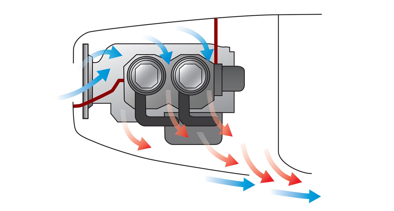
As the air leaves the airplane via the outlets, some of that momentum can be recovered. If the air exhausts flowing aft, the total drag of the cooling system will be less than the pure ram drag of the air going into the inlets. The outlets should be shaped to accelerate the cooling air to as close to free stream airspeed as possible and to direct the cooling air aft as it leaves the airplane.
A low-drag outlet system will be shaped so that the cooling air flows through a converging path inside the cowl that accelerates the air and directs it aft. The exit orifice itself should be oriented so that the air can leave the airplane flowing aft rather than down or sideways.
If the outlet dumps the cooling air out flowing down or sideways rather than aft, the cooling drag will be relatively high.
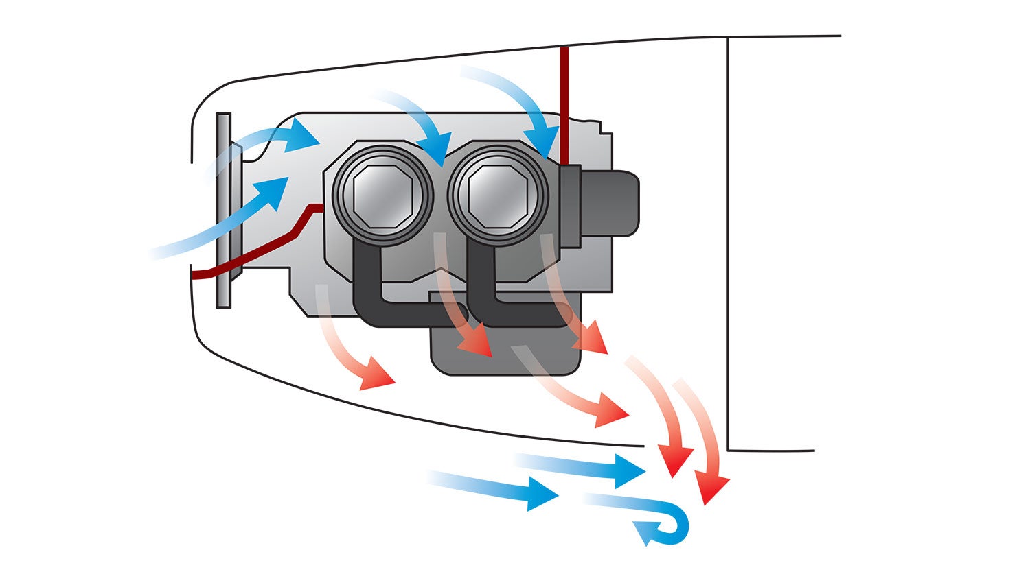
A common, high-drag approach to cooling air outlet design is to use a simple hole on the bottom of the cowl at the firewall to exhaust the cooling air. It’s common for the square corner between the firewall and the skin of the airplane to form the aft side of the outlet.
This is appealing at first because it is light and simple, but it is also draggy. Air leaving such an outlet will be directed down rather than aft. The system will have increased drag for two reasons.
First, the rearward momentum of the cooling air will be lost since the air leaves the airplane flowing down, rather than aft. No rearward momentum will be recovered.
Second, the cooling air exiting such an outlet will disrupt the exterior flow over the airplane.
If the outlet directs the flow aft, tangent to the skin of the airplane, the exiting cooling flow will mix cleanly with the exterior flow with minimal effect on the flow over the airplane components downstream of the outlet.
If the cooling air exits going straight down or at a significant angle away from the skin of the airplane, then the fountain of cooling air emitting from the skin will act like a spoiler, and the cooling flow and exterior flow will mix in a turbulent and chaotic way. This disrupts the exterior airflow and is likely to cause flow separation downstream of the outlet. This turbulent mixing and separation will significantly increase the drag of the airplane.
Disruption of the exterior flow is also a disadvantage of some design features used to reduce air pressure in the outlet and increase cooling flow. It’s not uncommon to put an air deflector or lip upstream of the outlet orifice to reduce the pressure at the outlet and promote additional cooling flow. While this works to improve cooling, the lip or deflector acts like a spoiler and adds significant drag to the airplane.
Next month we will take a look at the internal design of the outlet and variable geometry.


Loving this series of articles. Thank you Barnaby! Cooling drag is a kind of passion/obsession of mine. When I was building my Silence Twister G-FUUN, I researched cooling drag and ended up redesigning the entire cooling setup for my UL Power 260iSA engine. Making a sealed plenum, custom cowling from scratch (plug then molds) remote-ing the oil cooler and making a dedicated inlet scoop and ducts for that along with a cowl flap for oil temp control. In particular reference to this topic of outlet design I drew my inspiration from the best WW2 fighters (air cooled types) which had the outlets on the side and were optimally positioned and designed. My outlet directs the air parallel to the airstream and is also slightly a nozzle so accelerates the flow somewhat for pressure recovery. See my blog for more details: https://silencetwisterbuild.blogspot.com/2015/11/week-221-cowling.html
Good articles Barnaby. However you don’t make any explanation or distinction between dynamic / velocity pressure and static pressure.
The former is high at inlet and if slowed down by expansion can be converted in part to static. Static is the pressure required to drive the airflow past the engine. Dependent upon the outlet shape and area some can be converted back to dynamic and if directed properly can be ejected with minimal negative drag or possibly positive effect if it’s a jet. The shape of inlet and outlet determines how efficiently that conversion takes place and the objective must be to do so as efficiently as possible. If that is achieved then the total flow through the engine can be reduced and maintained at the level required to cool sufficiently
The driving force behind the airflow is the positive dynamic from forward velocity that can be aided by a negative / under pressure at the outlet according to shape. If the flow is too high it can detract from the aircraft performance too. It can be useful to measure the static pressures in the upper and lower plenums whilst in flight and in different attitudes such as climb out to ensure sufficient and not excess flows. That’s the purpose as I’m sure you know of cowl flaps etc. the effect of an enclosed upper plenum is generally to increase performance through increased efficiency in cooling airflow.
Comments are closed.