Securely holding small parts for machining is always a challenge. The solution may be to use a work-holding gadget such as a pin vise or peg clamp, make a custom fixture or, in the case of this month’s project, stack up two accessory devices—a rotary table and a 5C indexer—to accommodate the job at hand. Before deciding how to proceed, the machinist needs to consider the material being machined, how much needs to be removed and what the expectations are for tolerances and surface finish. These were the considerations I had to contemplate recently when deciding how to machine an arc on a batch of nut plates for a spinner backplate.
Background
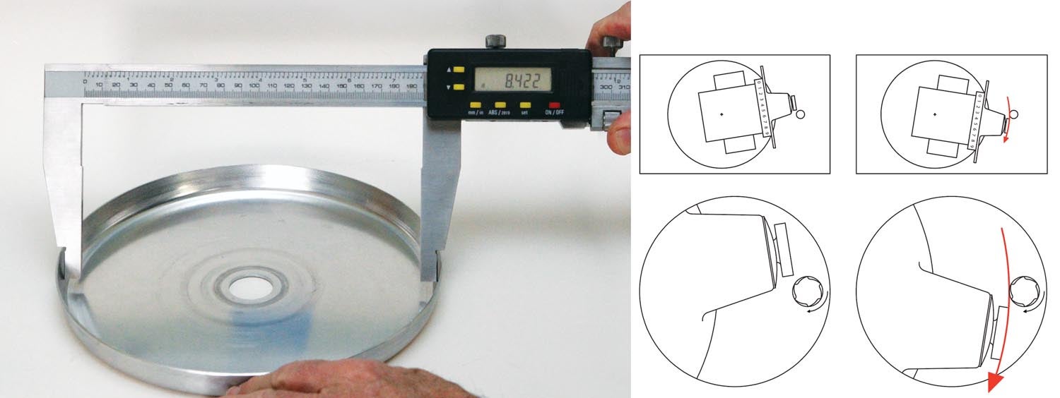
Since moving to the high desert of northern Nevada a year ago, the wood cruise prop on my Jabiru has proven to be less than ideal for trips over—or into—the Sierra Nevada, such as to South Lake Tahoe for mountain biking. I have a composite ground-adjustable prop that can be set to give a rate of climb about twice that of the fixed-pitch prop, but I had been procrastinating because the fiberglass backplate that came with the spinner (also fiberglass) for the prop was, to put it bluntly, a lumpy pile of junk. When installed, it caused the propeller blades to be off track by more than ¼ inch at the tip (1/8 inch is the specified maximum). With the prop bolted directly to the crankshaft flange, the blades tracked perfectly. So I knew it wasn’t the propeller, hub or crankshaft. Checking the thickness of the backplate at various points provided confirmation: There weren’t any two places that measured the same thickness. It appeared to have been laid-up in a slump mold using chopped fiberglass matting, with little regard for consistent thickness or having flat and parallel faces. Considering both factors are necessary for propeller blades to track in line, that’s not a good process.
So before swapping to the adjustable prop, I had to either fix the fiberglass backplate (Plan A), make one from scratch (Plan B) or buy a new one (Plan C).
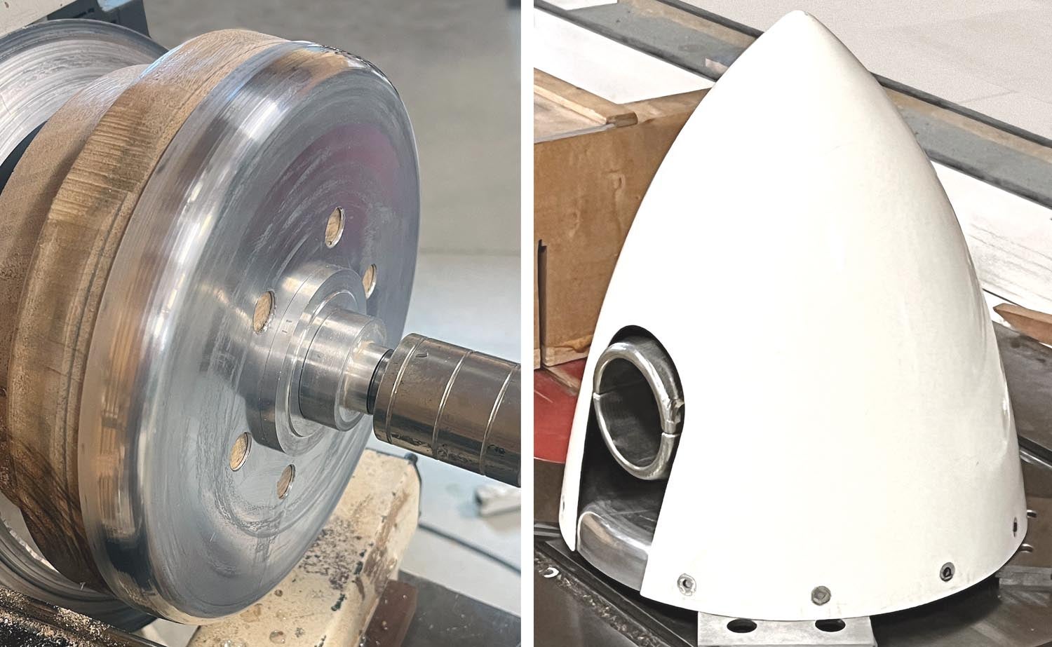
Plan A began with the idea of filling and sanding the low spots, but I instead decided to try to use a lathe to fix the uneven face by “scraping” off the high spots. That was a bust! Machining fiberglass may be possible with carbide tooling and a heavy industrial lathe, but I had no luck with a small bench lathe; the rock-hard fiberglass quickly blunted my high-speed steel bit. Instead of cutting, the tool simply bounced over the (many) high spots and chattered badly.
On to Plan B: Spin a new aluminum backplate. The backplate that I had been using was the one I made for “Spin Class,” my column in the October 2017 issue of Kitplanes. Since I have already covered how to spin a backplate, this month’s project will focus on modifying nut plates to precisely fit the curvature of the backplate flange.
For the backplate I made in 2017, I purchased a set of aluminum nut plates with fiber-lock inserts from a supplier on eBay. I hand filed each one to fit the curve of the backplate flange. Hand filing was a tedious job and the results, while passable, were not precision. For this backplate, I wanted to step it up a notch.
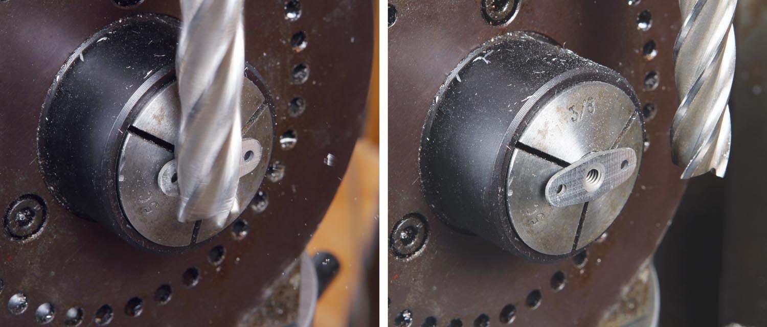
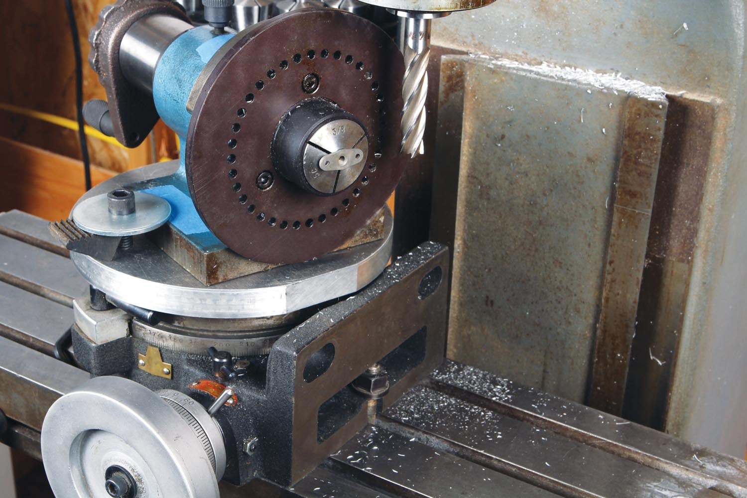
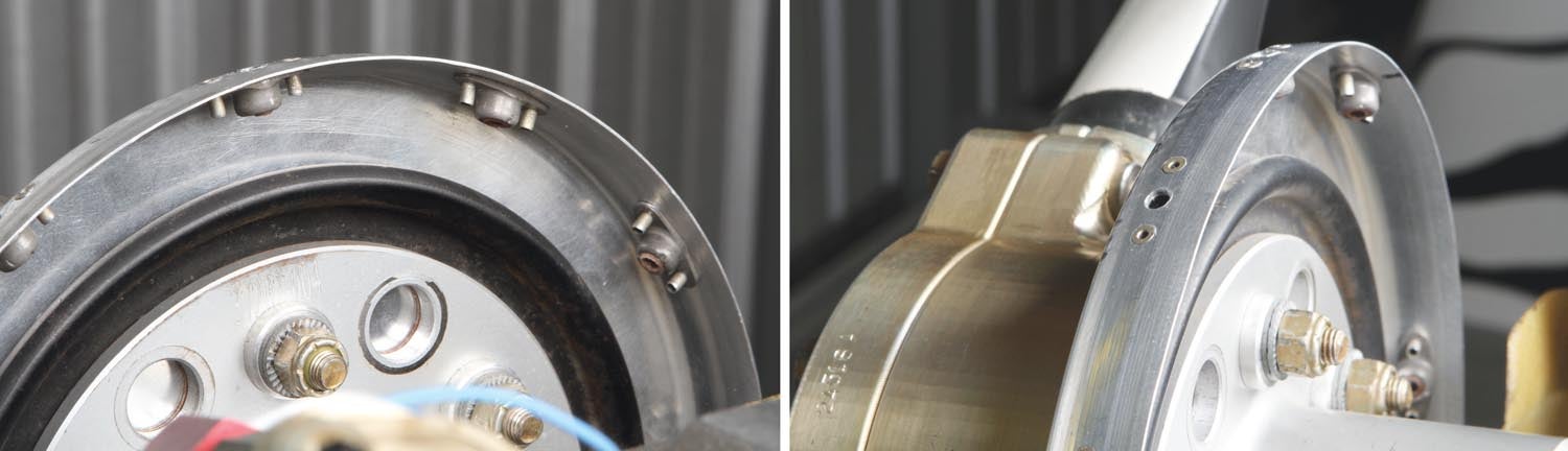
The particular nut plates I used*, again purchased on eBay, have a cylindrical protuberance that, while short and otherwise not so great for clamping in a traditional vise, fit a 3/8-inch collet. This allowed me to use my 5C spin indexer as a clamping fixture. This project doesn’t require indexing, so a 5C collet block or collet angle fixture would work just as well. The 5C indexer was then clamped to the rotary table, the center of which I had offset from the milling cutter the radius of the backplate flange (measured where the screws would go). The indexer was positioned on the rotary table so that the centerline of the nut plate just kisses the milling cutter. At this point, I reset “zero” on the dials, rechecked that all the hold-downs were tight and grabbed my safety glasses to start cutting metal.
Since my rotary table is a relatively inexpensive import model and has a bit of backlash in the mechanism, I always make the cut direction “normal.” In other words, moving the workpiece against the cutter rotation. The alternative to normal cutting is called climb cutting, which is feeding the workpiece with the direction of cutter rotation. If you climb cut with a feed mechanism that has backlash, you run the risk of the workpiece “jumping” (self-feeding into the backlash) when the cutter engages. This sudden movement at the least will cause the workpiece to get messed up. If you’re making a heavy cut on steel, it could possibly overload the cutter, which might cause it to break off. When in doubt, don’t climb cut.
While this may look like a lot of rigmarole to fit 10 nut plates to a backplate, the precision fit was well worth the effort. Simply riveting them without having them conforming to the curve would cause the edges to dig in and deform, in the form of divots and flat spots, the backplate. Divots, especially on spinning parts subject to constant and varying centrifugal forces, would be likely starting points for stress cracking and eventual failure.
That’s it for now. It’s time to get back in the shop and make some chips!
*#8-32 Installation Kit AN366DF832A (20) Nut plates, (40) Rivets, (20) SS Screws


Hi Bob:
I always learn something from each article – thanks!
The only thing I would add is to use AN427AD3-xx rivets to attach your modded nutplates to the spun spinner – great job on that, also!
Any composites between the prop & crank flange are not good as friction will heat up the resin past it’s Tg,
allow it to crush, and you’ll lose the bolt pre-load (and prop). In addition to the un-even surfaces…
Regards,
James
Comments are closed.