 Now with the satisfaction of having the tail section complete, it was time for us to figure out how to “attack” the wing build. Mike and I literally spent a full day rearranging the workspace to move tail parts out and the wing parts in. Plus cleaning, which is actually a continual process. Once we had found the wing parts in our inventory and had prepped our big work table, we decided to start on the left wing. Why? This was the orientation pictured in the parts manual!
As much as most builders want to jump right in and get creating, I learned that the prep work takes time, but it’s worth the effort. Getting all the parts together and understanding how they fit together is a big part of organizing not just your workspace but your thoughts as well. Yes, there are elements of the prep that don’t seem so glamorous, like sticker removal (de-gooing them), but these are small steps that you want to be done correctly from the start.
Mind Work
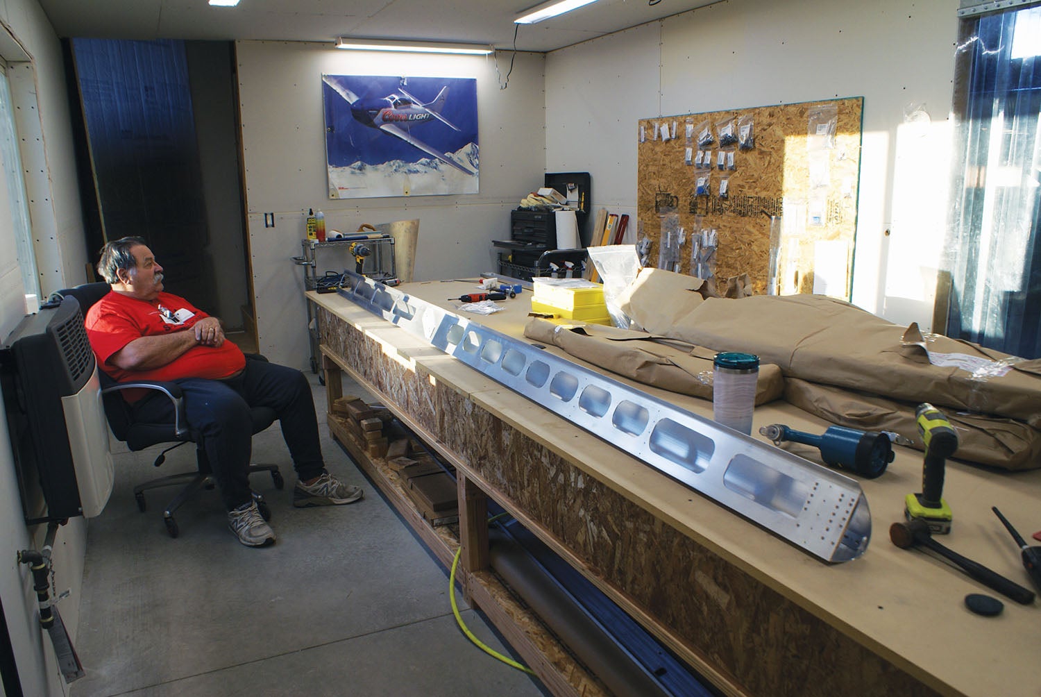
Part of forming the right builder mindset involves thinking ahead and making sure you have what you need when you will need it—nothing wastes time like a mad dash to find a part or a tool. During our down time, Mike likes to have what I call his “cogitation time,” where he just looks off into the distance and thinks about the build. (At least that’s what I think he’s thinking about!)
In between the tail components and the wing we were about to start on, Mike was considering the size of the pieces we’d be working on and thought about the support pieces and work tables. He concluded, “Let’s use some steel construction beams rather than wooden 2x4s.” This would give us a solid foundation to work from rather than relying on wooden 2x4s—in Nevada they have a tendency to dry and twist, which defeats the purpose.
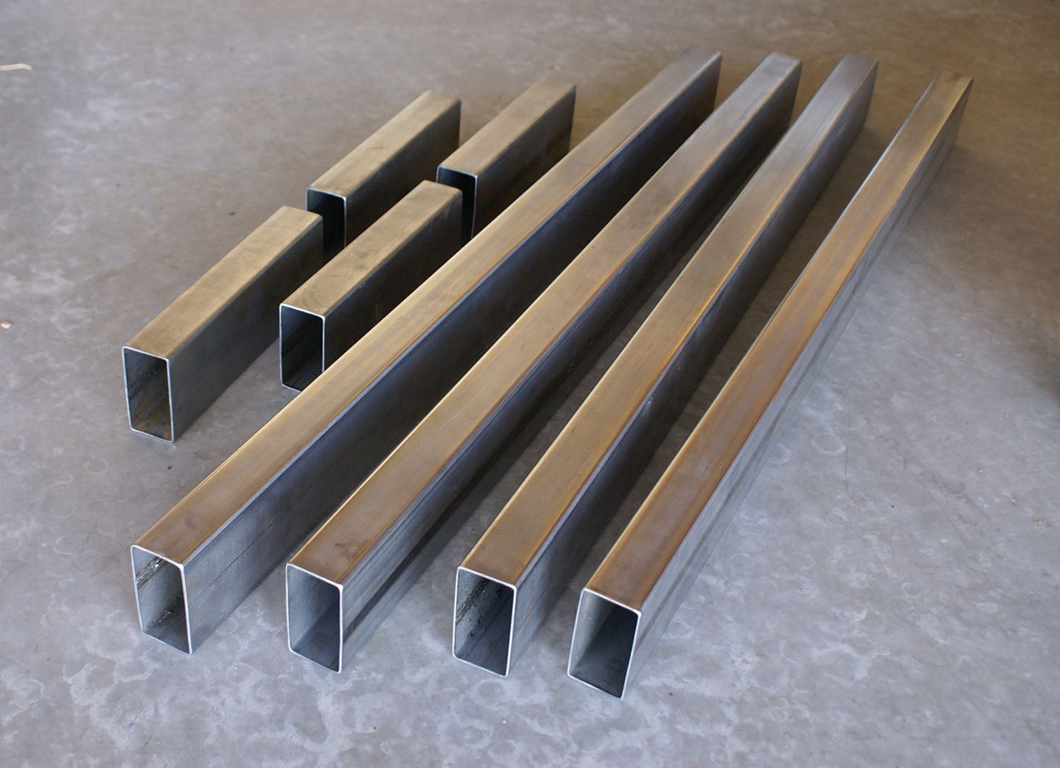
We sourced rectangular steel 2x4s from a local supplier and took a day off from building to run into Reno and pick up a 20-foot piece of 2×4 steel that the supplier cut into two 10-foot pieces, thanks very much, and brought them home, where Mike further cut them into four 4-foot and four 1-foot pieces. These steel fixtures would prove to be essential to building parts without twist. I wish we had these from the get-go!
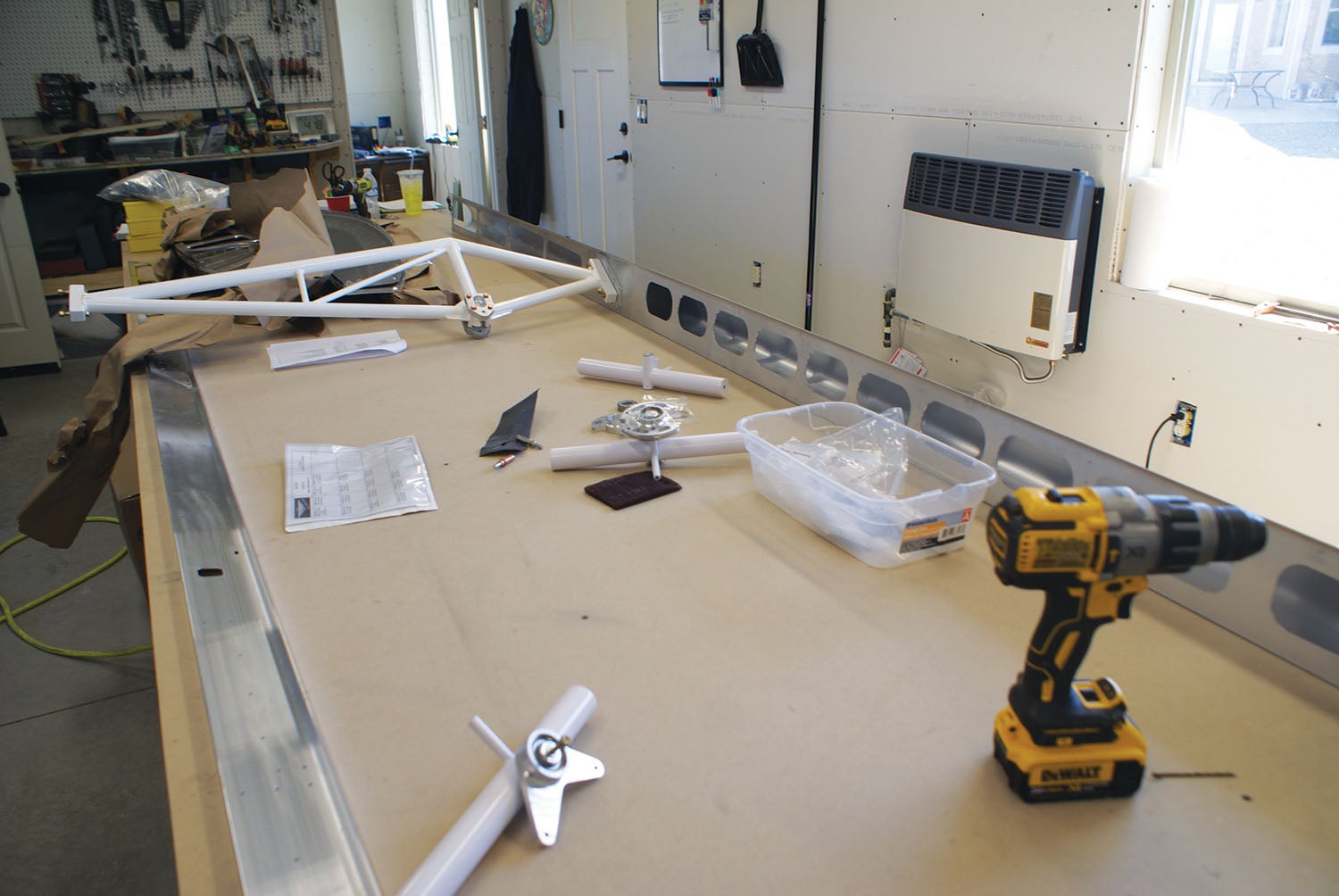
Another product of Mike’s cogitation time was this question: “What do we do with this wing after it is done?” The answer: We’re going to need a wing cradle to store them in. Turns out, we have a friend who lives about 30 miles away and who just completed a RANS S-20 Raven. Mike decided to see if he still had his wing cradle and, sure enough, we got lucky. Not only did he still have it, but he was willing to deliver it and let us use it with the understanding that we would pass it along to another builder in the future. What a deal, and further proof that airplane builders are the best. He brought it up to us the next day in pieces and parts, showed Mike how it went together, then we gave him a little tour of our S-21 build.
That, by itself, revealed an interesting part of this process. Interest in the community, especially with a new model, can be strong. Everyone wants to drop in and see your progress. We have a great time sharing the S-21 build with friends who have shown up from many neighboring communities and states. It has really generated a lot of interest.
OK, the Wing!
We got going with the left front and rear spars and doublers, and the correct orientation of the pieces. Because there are different rivets used throughout the wing, you have to pay close attention to which rivet is being used where. The manuals are useful to assist in the layout and orientation. But, still, I had to learn how to look at the diagrams in the parts manual to read them properly to know this information. It was pretty straightforward (most of the time)… just takes some getting used to.
During mating of the strut truss to the front spar, I had my first experience of where my “tiny hands” were quite useful. I had to literally stick my hand and forearm into the front spar to get the nuts screwed onto the bolts for the lift-strut assembly. It was a tight fit for me and there’s no way Mike would have gotten his arm in there. Advantage, me.
When it came time to get the ribs prepped, we had a good system of me working on cleanup—ensuring the inventory stickers had been removed, the skins cleaned and any sharp edges deburred—and while I did that, Mike was working on the aileron and flap bellcrank assemblies and flattening the ribs with the fluting pliers. It all needs to be done, it just takes time. It was interesting getting the correct rib in the right place because the flanges were pointing right and left and the order was not exactly logical, so it was easier for me to lay the ribs out in the proper order and number them to keep their locations straight.
When it was time to rivet the flap hinges to the ribs, we noticed we had only four flap hinges instead of the required six. This turned out to be my bad. I had checked off the part number and the bag during inventory, but I did not stop to count the number of pieces in the bag. Very easy oversight. Another thing we noticed was that the inboard/root flap hinge was supposed to have a hole in it for the fuel hose to pass through. On ours, there was no hole, so we ended up contacting Shelly at RANS. Turns out the early kits did not have the hole, and the initial RANS solution was to send us a kit to punch the hole ourselves. But when the package arrived, it was the root rib with the hole already punched. That’s service!
It turns out that waiting for the new hinge wasn’t going to hold us back. The fuel tank installation would have to wait due to a modification pending the fit of the tank to the spout area. This is part of the reality of building a new model of an aircraft. There will be modifications, you can count on it. RANS has been very accommodating to make sure that we had what we needed.
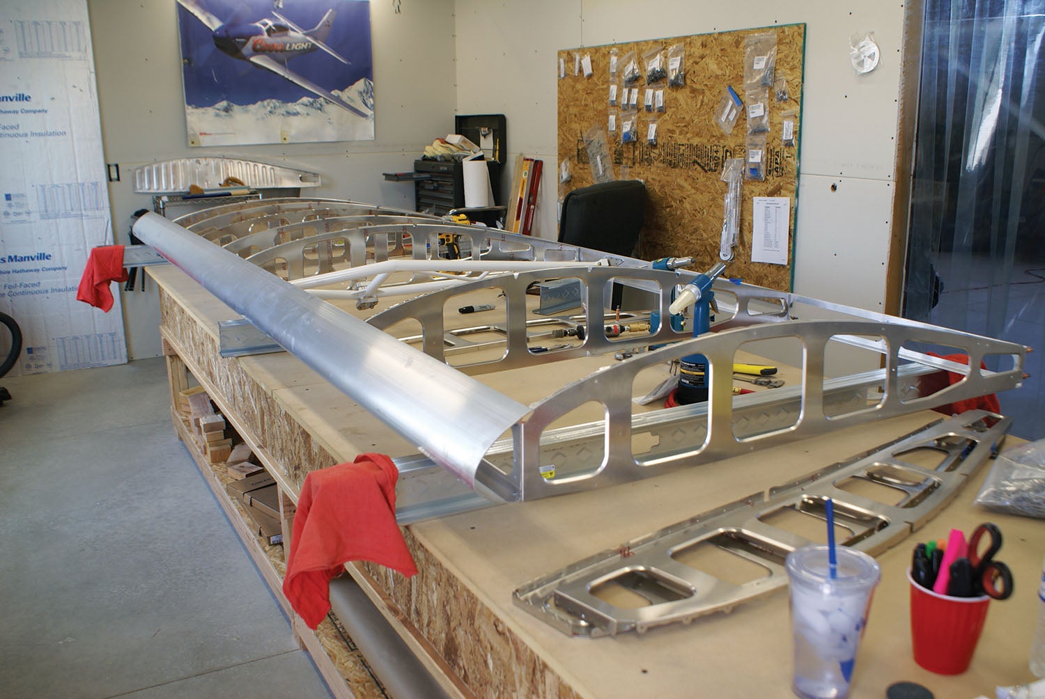
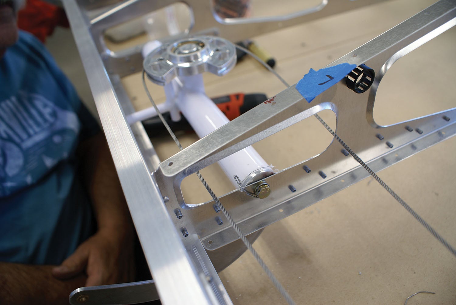
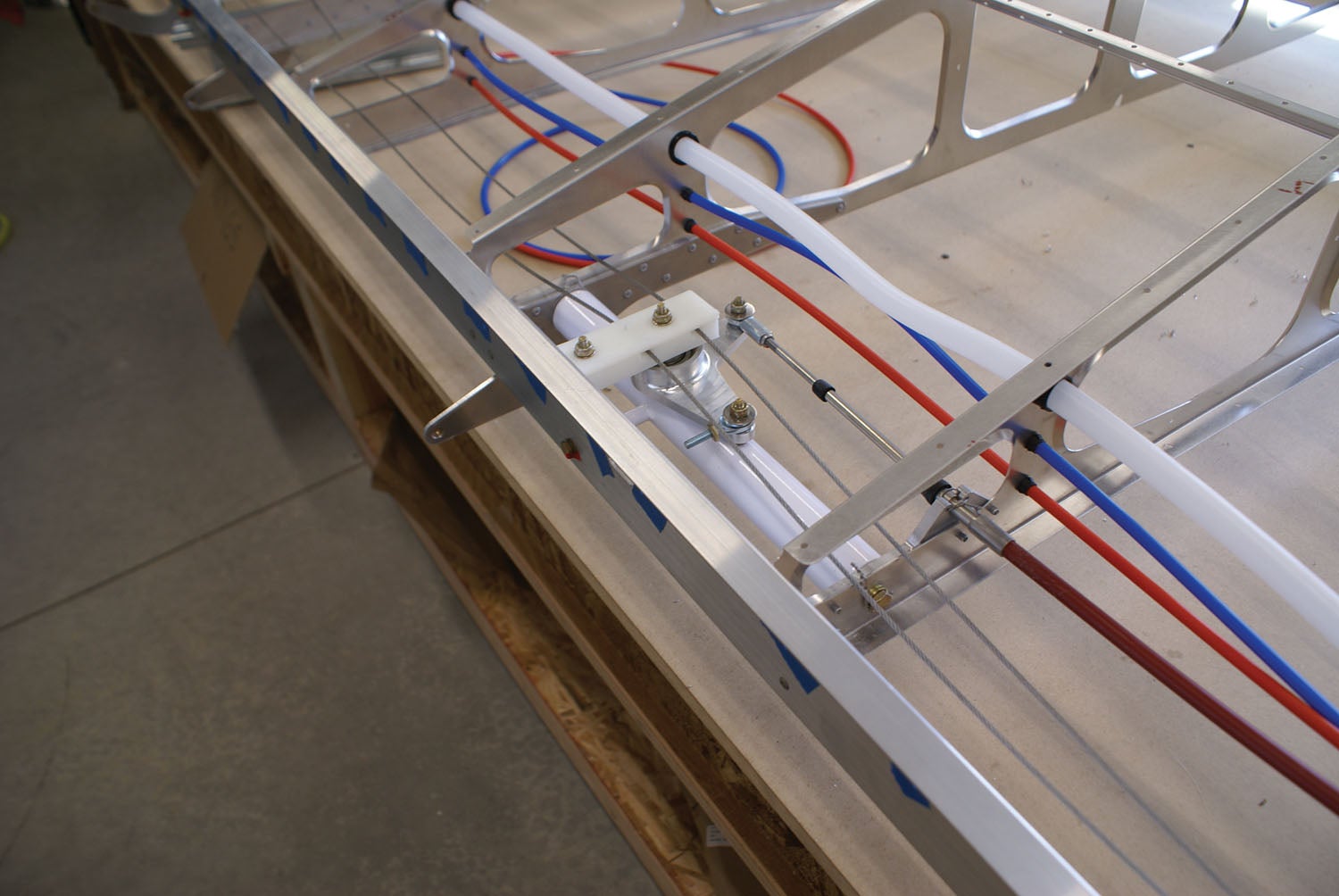
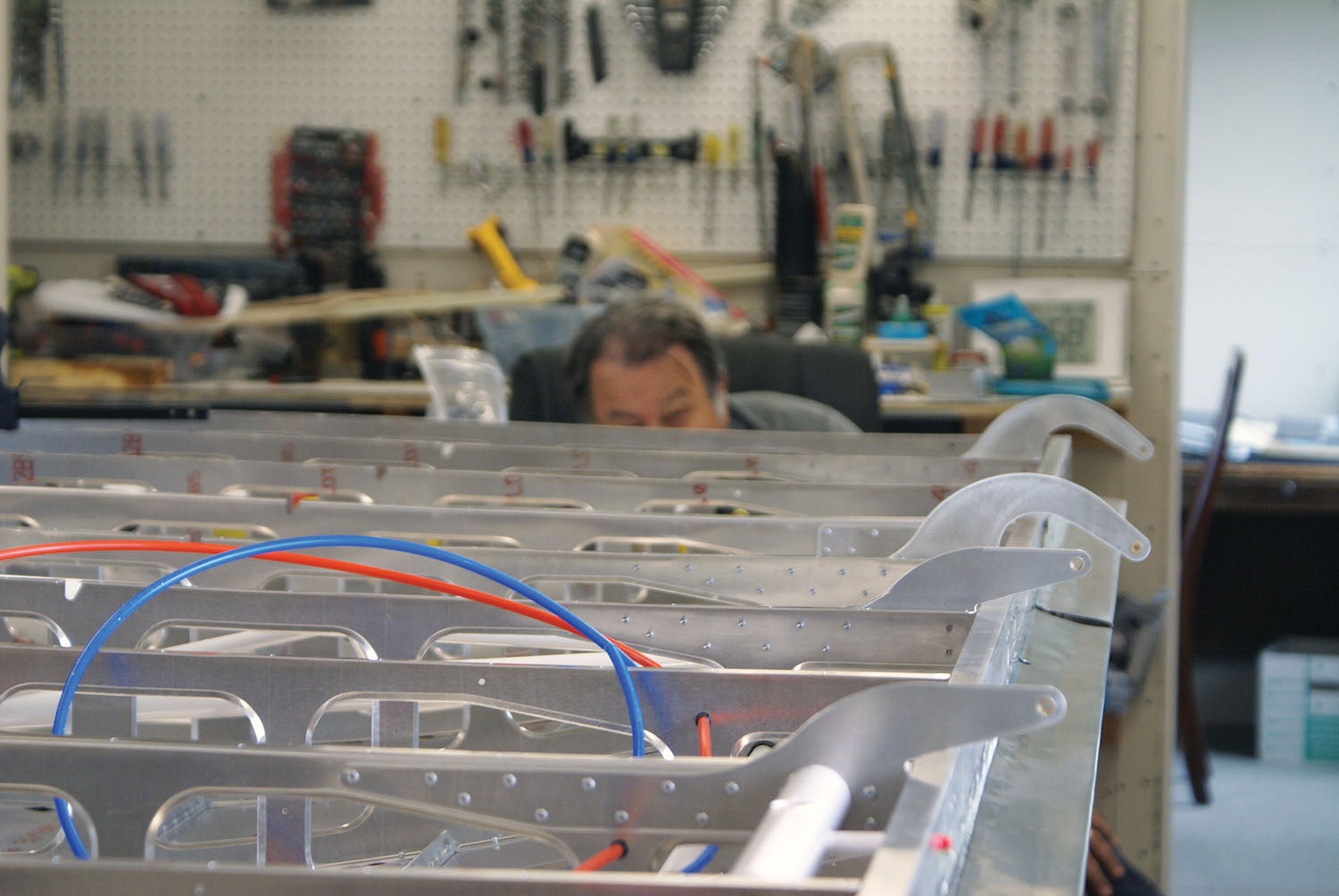
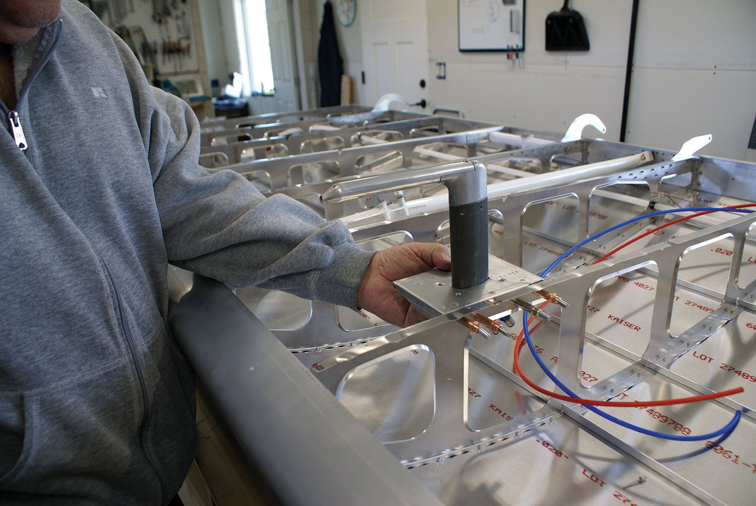
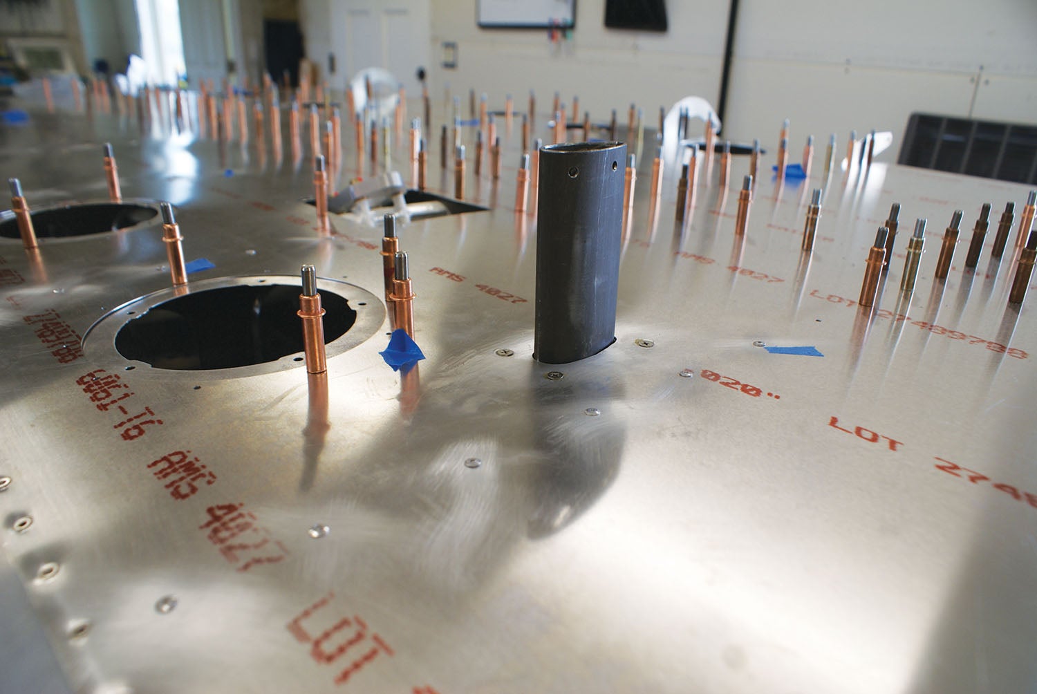
After getting the basic frame of the wing constructed, front and aft spar with truss attached, ribs going the correct direction and riveted, construction for the inner workings could begin. To have lighting at the wingtip and wires for the ADS-B out, Mike drilled a hole through the aft portion of the ribs, lined the holes with snap bushings to protect the tube from the edge of the rib and inserted a tube for the wiring that we would install later. Two tubes for the pitot system were placed through holes drilled into the rib and protected with snap bushings also. Bellcranks for the flaps and ailerons were mounted, along with the cable for the aileron and Teleflex cable for the flap, and then all were safety wired in place.
It was time to step back and check that all the inner workings of the wing were in place. We went through the pre-skin checklist to make sure that the all was in place—and it was. It makes a lot of sense that they include this checklist in the manual because once the skin is on this huge wing, you really don’t want to get back in there. Even though there are access panels, it’s so much easier to make changes and refinements with the wing open. So, our advice is don’t rush. There’s no massive hurry to close the wing.
Skinning in the Game
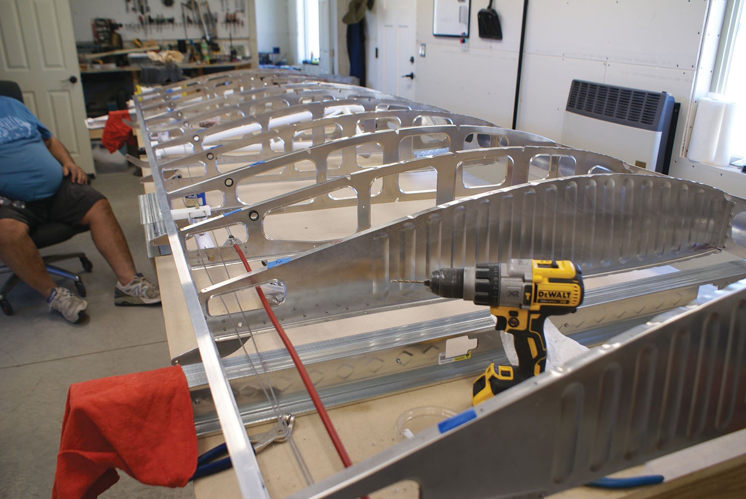
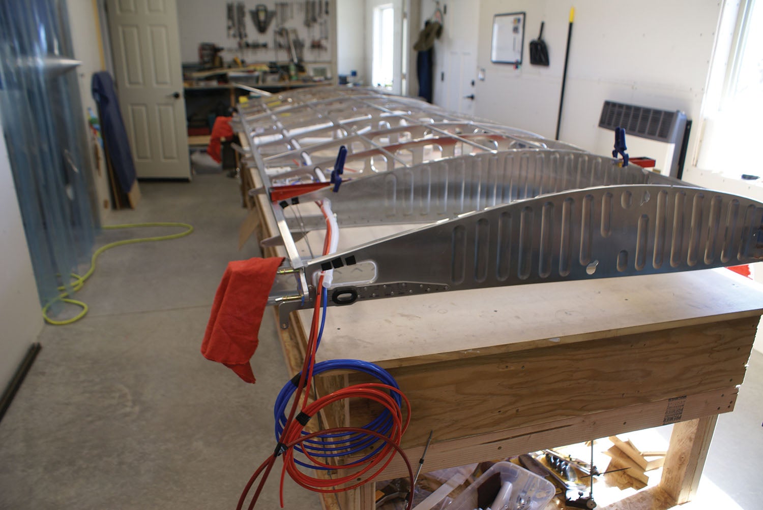
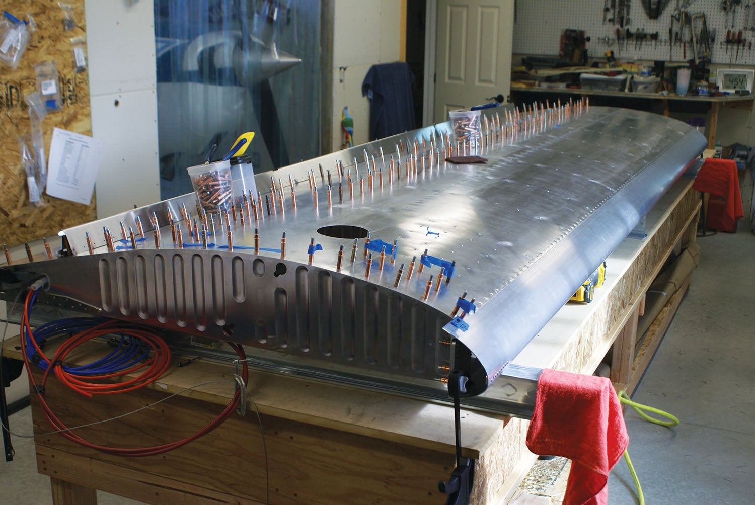
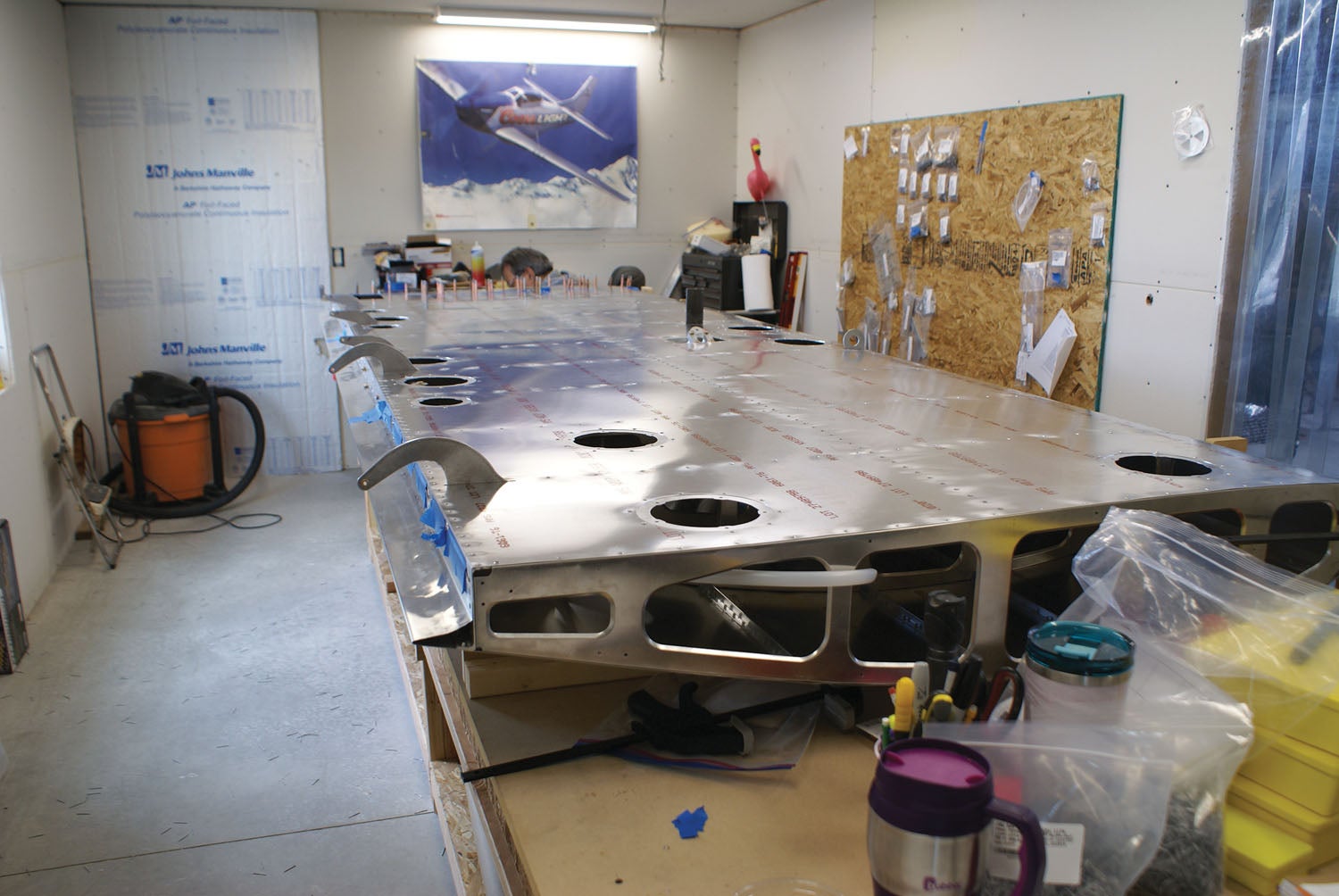
Still, that time comes—skinning the top side of the wing! In prepping, we secured all the cables and tubes coming out of the root of the wing and got the stringers in place. The stringers go parallel to the span to support the wing structure. Since this is a giant sheet of aluminum that you really don’t want bent, here was another job that required the assistance of neighbors. Did I mention that aircraft-building neighbors are the best?
Once the skin was placed on the wing, we had to fuss around with the strut truss and leveling to get the alignment flat and without any twisting. This is a large piece to be working with. It was pretty mind boggling to me, but at the same time really fun seeing it come together. There were a few new tools used during this part of the build that I can understand the need for. For example, you want to have a smooth leading edge to reduce drag, so the skin that overlaps the leading edge—which is really the main spar in this design—needs to be slightly bent over with an edge-forming tool. Also, on the S-21, the main skin-to-leading edge mate receives flush rivets. The use of the edge-forming tool is a bit of an art that takes practice. We had a couple of spare pieces of aluminum we used for practice and that was really helpful. Better to mess up on scrap than your own wing skin.
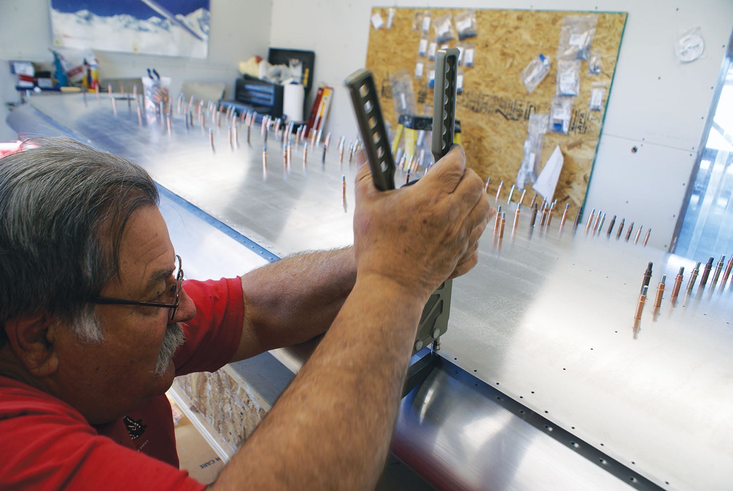
Flush riveting was something new for me on this project. Of course, it’s not just grabbing a different kind of rivet. Although we were using blind or pull rivets, the underlying concepts are the same as they are for driven rivets as typically used on RVs. We had to countersink the thicker metal of the spar and create a matching dimple in the thinner sheet over the top. It’s here you want to slow down and make sure your work is the best it can be. The big difference is in the last step, where the pulled rivet is secured from the outside, which is really a nice thing when you’re riveting round a tight radius or where access to the back side of the work is difficult.
It’s Tops!
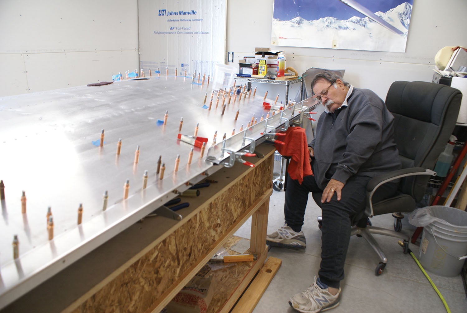
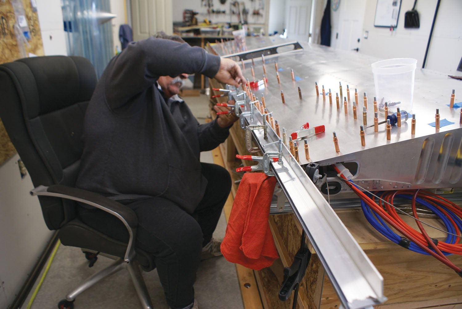
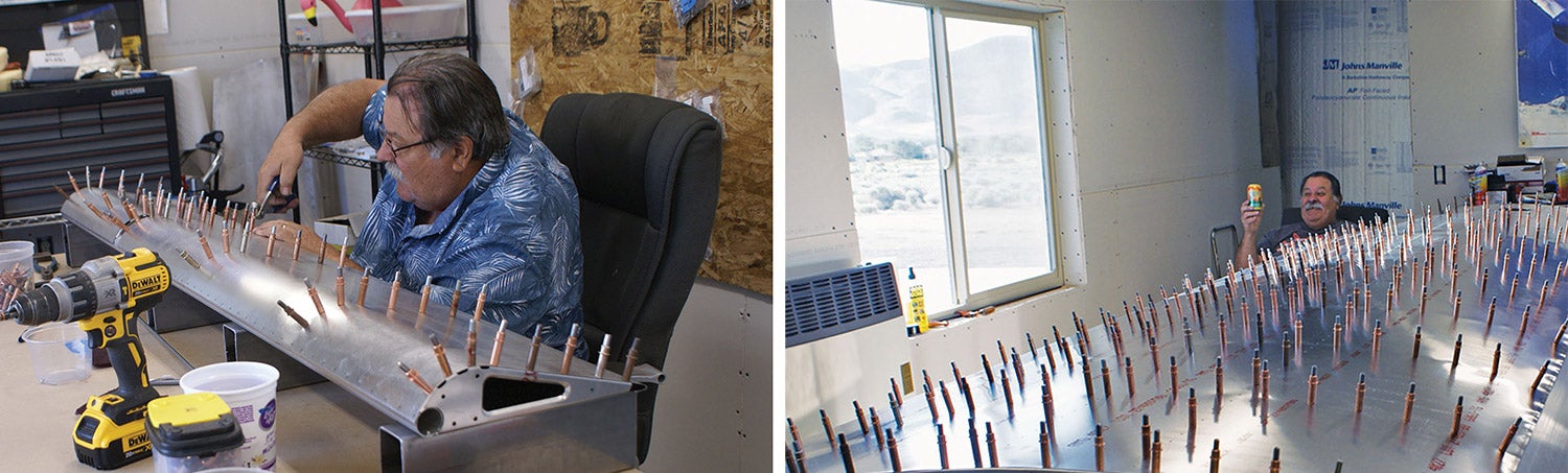
Getting the entire top skin riveted was quite backbreaking and because there is so much surface area, it takes way more time than I was anticipating. I did all the riveting and Mike would call out if I had the rivet gun misaligned. I could tell when it was time to quit if I had too many rivets that were “proud,” as my neighbor Louise put it. There’s a simple gauge: If you can get your fingernail under the rivet, you need to drill it out and try again, I was told. There was one time I remember that I had three bad rivets out of about the last 10. I said to Mike, “three strikes, you’re out” and called it a day. I also have arthritis in my hands and was hurting from all the Clecoing and riveting, so you just have to know your own limitations and not continue pushing. The whole project will be there tomorrow.
Before finalizing the top skin, there was one facet we needed to figure out: the “dreaded” gap seal. On the S-21 wing, there’s a roughly triangular piece that runs the length of the wing, spanwise, and closes the gap between the trailing edge of the upper skin and the flaps and ailerons. It needs to be flush to the wing and follow the upper skin’s contour. I frankly had never really noticed this part of a wing before, but so be it. It comes as a piece that is not bent to the final shape, so the builder needs to finalize it.
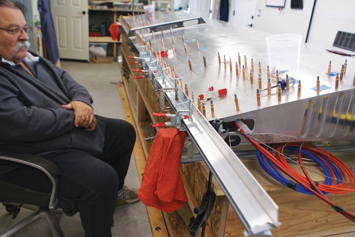
This was the most difficult part of the wing build. We attached it with Clecos and consulted our neighbor Paul, regarding what we thought the best approach was for us to bend this long flimsy piece of aluminum into the desired shape. The conclusion was to get two long pieces of angle aluminum, clamp one section of the three sections at a time with about eight to 10 clamps, squeeze it down a bit, unclamp them, check for the angle it had bent to and repeat as needed to achieve that flat wing-to-gap-seal surface. Of course, you had to go slowly to not overbend the metal.
Oh, but you’re not done yet. While the top surface is flat, the lower surface of the gap seal has to be arched to allow aileron and flap movement. To get the correct curvature to the bottom side of the gap seal, Mike would take the rounded end of a screwdriver or a ball peen hammer, wax it up with beeswax and run it on the underside of the gap seal section while I pushed down on the topside with the angle aluminum. What guesswork! The end product was flat on the top, but pretty ugly on the underside of the gap seal. Not to worry. This part would be covered by the flap and aileron, so no one—but us—would know how ugly it was. It is my understanding that this part has been since redesigned by RANS.
Our Time in Space
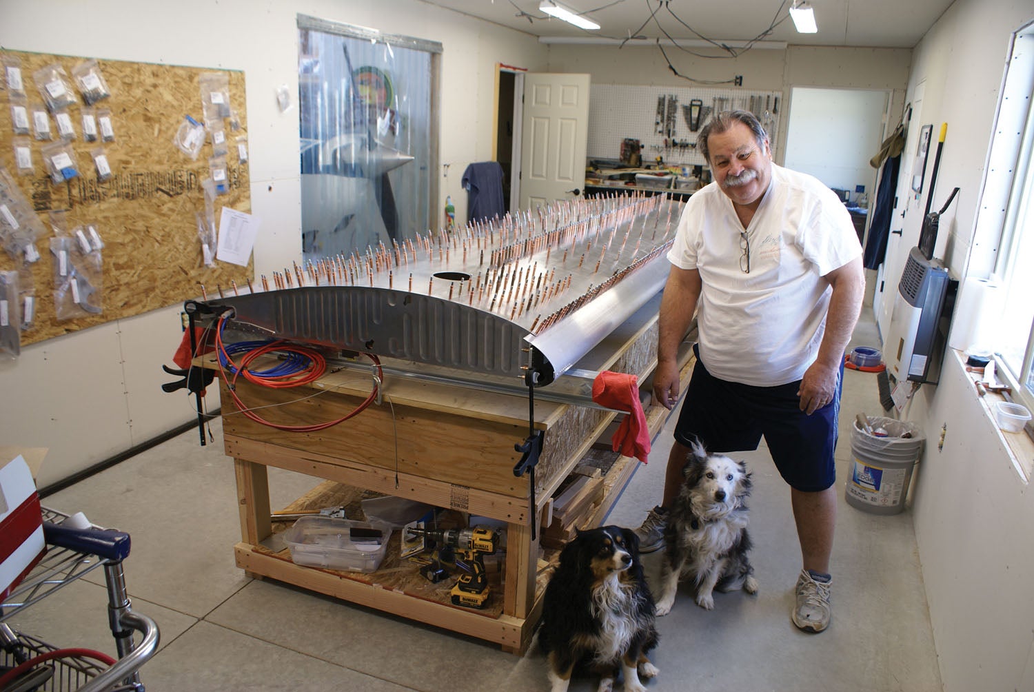
Revising the workspace was needed when it came time to do the bottom skin, mainly due to the curvature of the top of the wing. Wooden jigs are provided with the kit to hold the wing in the proper position for working on the underside of the wing. With jigs assembled and neighbors once again enlisted to assist, we flipped the wing and placed it topside down in the cradles. Now we were ready to get to the bottom skin.
The main difference in the construction of the bottom skin for us is that Mike had decided he wanted a pitot system that included angle-of-attack capability, and that pitot head is a bit beefier than the standard issue from RANS. That, in turn, required a strengthening modification to stiffen the bottom skin and accommodate the mount. We also had to place it carefully to not interfere with anything else inside the wing. Once you deviate from the original design and plans, you’re on your own.
All this, of course, made me quite nervous cutting into the skin where there were no directions to follow. I just had to trust that Mike knows what he’s doing, even if that includes him figuring it out along the way! He sought out consultation on his design, once again with neighbors, and it ended up looking just like it should.

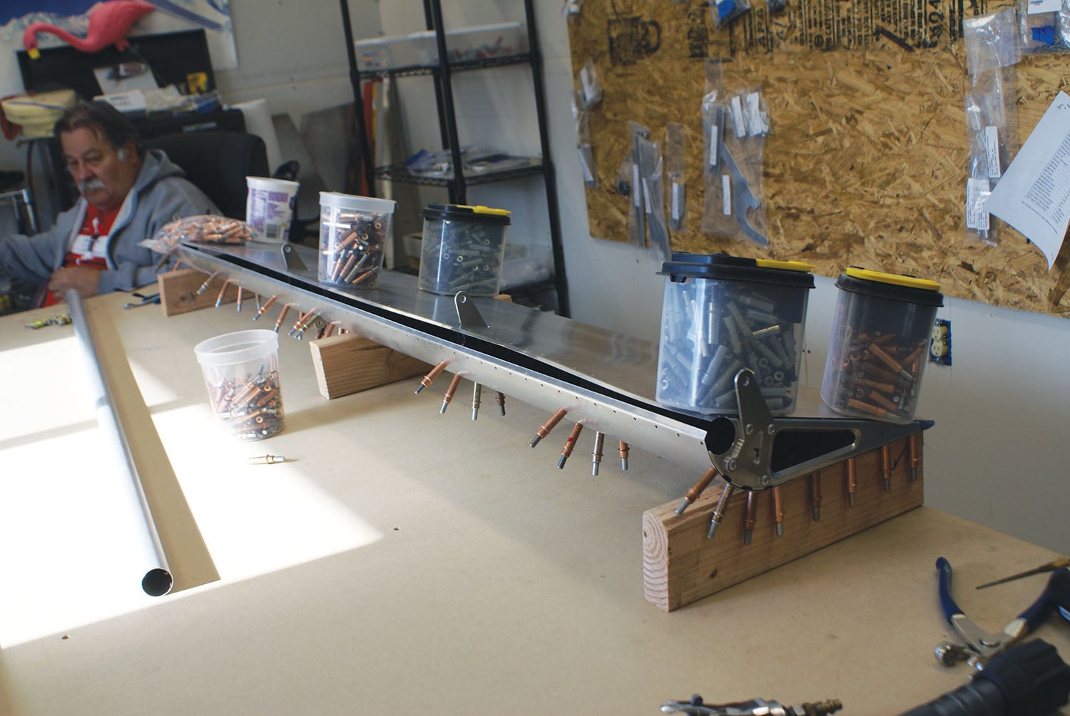
The remainder of the underside of the wing was more of the same as the topside, lots of riveting, with long, tiring hours of repetitive work. We were not able to finish the wing off with the fuel tank at this time because there is a modification to the neck of the tank pending from RANS, so we put the left wing to bed in the cradle and decided to work on the left flap and aileron next. We whipped these out no problem. It was nice to work on a small part for a change.
Hits From the B Side
It is rather daunting to start to build another wing, but at least we had some experience this time. I had great pleasure reading the manuals this time because I understood them better. This wing was a bit simpler due to the fact that we didn’t have to deal with adapting the pitot system. Many more hours of Clecoing, drilling, deburring, riveting and leveling multiple times ensued, and soon we were done with the right wing. Does that sound like one of those time-lapse movies where something that takes days is completed in minutes? It almost felt that way since we were both familiar with the steps and could look ahead at the potential problems. Confidence and experience both come as you build.
Now with both wings done and put to bed, we wrapped things up by getting the second flap and aileron built without any issues. The aileron and flaps were covered in blankets, set aside for safe storage and the workspace was ready for the next step.
I think that as a pilot hopping into a manufactured plane—for me, a Cessna 172—I didn’t appreciate all that goes into what’s inside that wing to make everything work correctly. Building the S-21 opened my eyes to how much is involved. Oh, and with many long hours of riveting to my credit, I got a new nickname: Rosie.
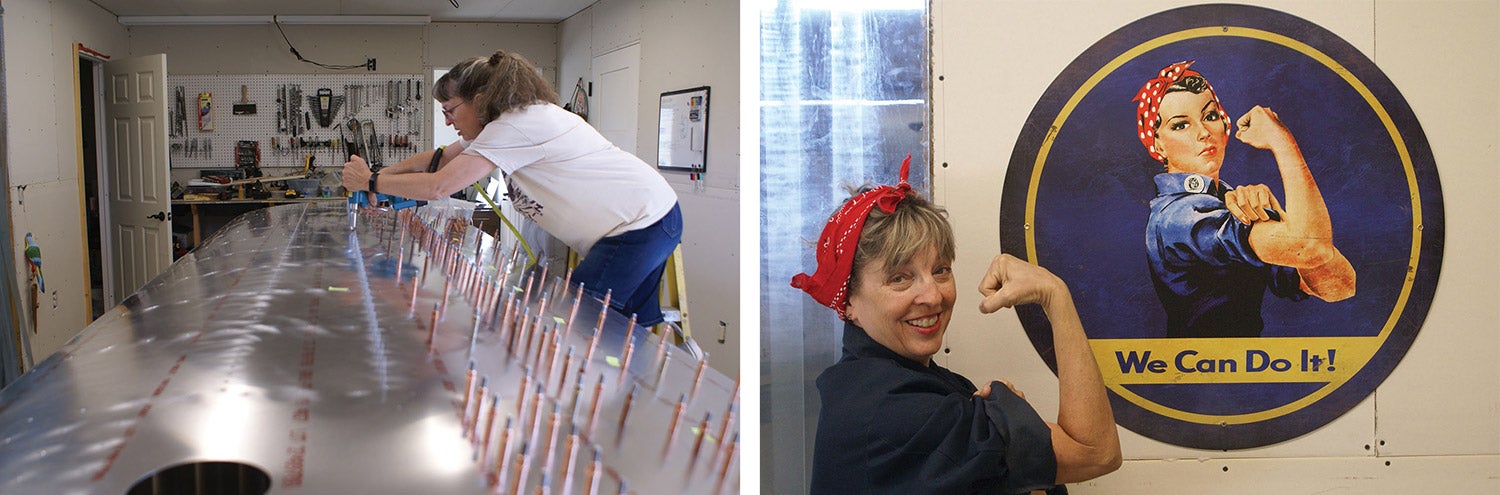
Photos: Laura and Mike Starkey.


