 Rather than tucking them away right after inventory, we brought the empennage (tail section) parts straight into the workshop. The manual says that the rudder is usually the best place to begin, so we agreed to this plan. A favorite saying of Mike’s is, “How do you eat an elephant? One bite at a time.” I know it is a common phrase, but oh boy—did we have an elephant here!
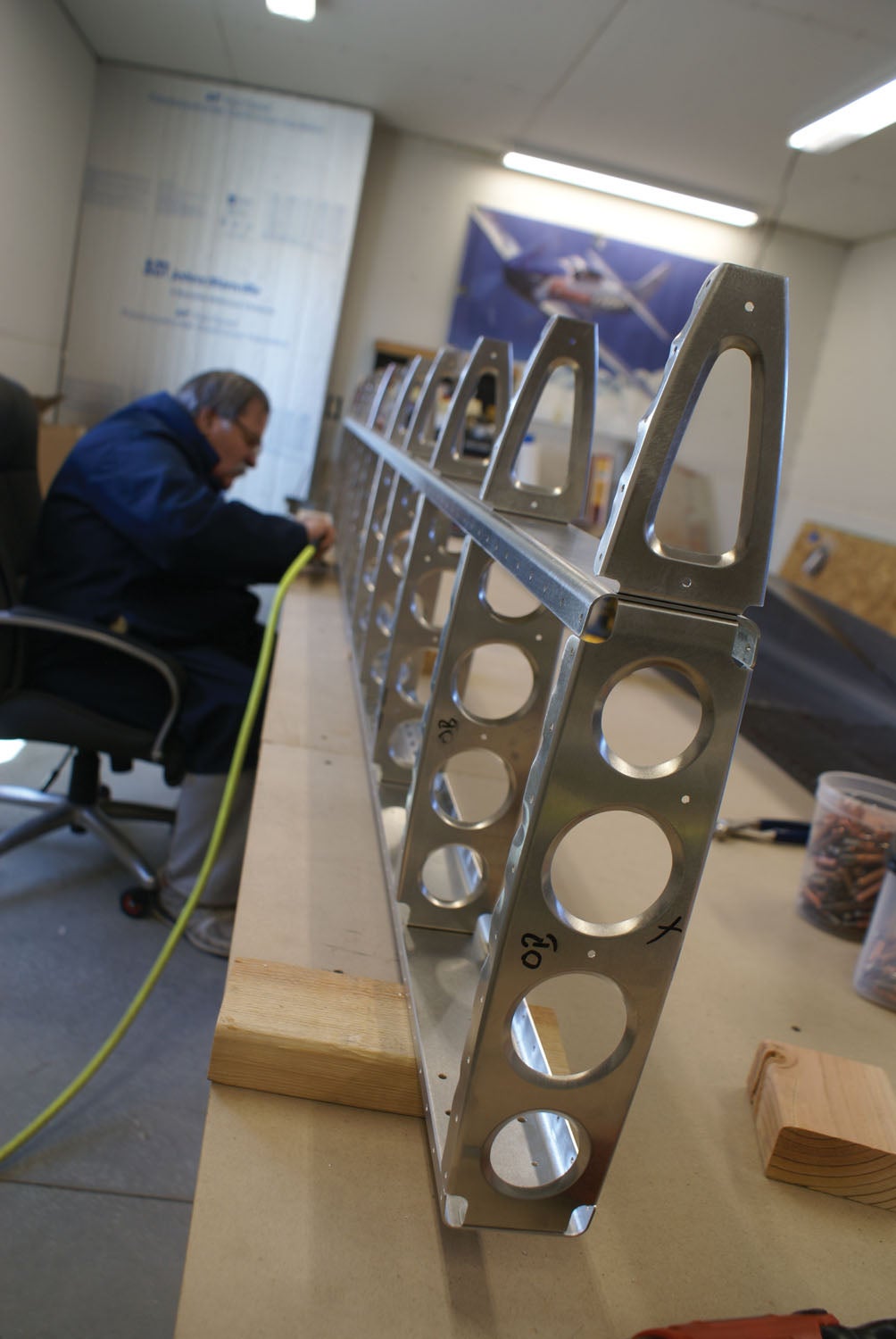
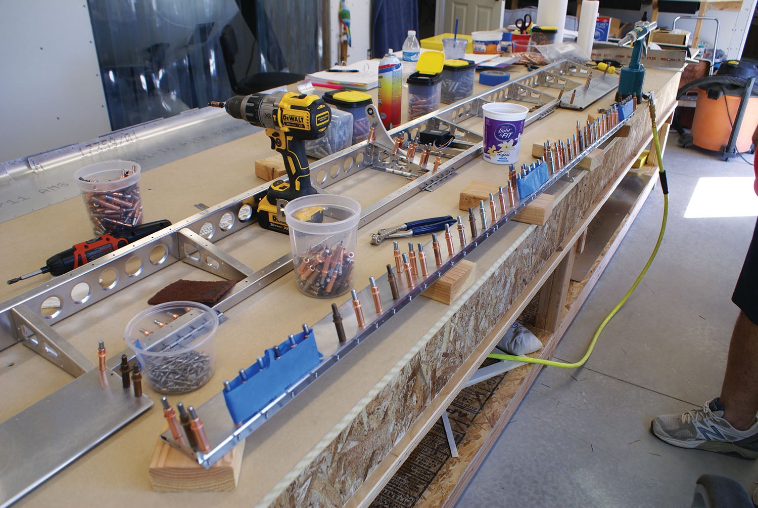
To get started, we organized the larger skins and parts below the workbench, with the small parts and rivets stapled to the wood board on the shop wall. The labeling of the parts from RANS is very straightforward, so this was extremely helpful to me in organizing before building. We didn’t waste any time. The very next morning following the days-long inventory, we began.
And Here We Go
The assembly manual has a “getting started” section at the very beginning, letting you know some basics of building an aluminum airplane. Since this is my first build, I wanted to start out right. There were some extremely good tips for how to proceed with each step of the build that I relied on heavily, such as having each of the manuals (text, parts and figures) open to the same part of the build, laying out all parts for that portion of the build and envisioning how the pieces are going to come together before you actually start assembling. Among the other useful tips: keep parts level during the build with wooden blocks as needed and maintain a clean work area at all times. Then there were tips on deburring all those metal holes and edges. It’s worth mentioning that RANS has done a great job with the manuals’ organization. For example, the basics of metalwork are not repeated each time you need to do them. So you learn the basics of deburring once and let practice take care of the rest. But the reference is always there if you need it.
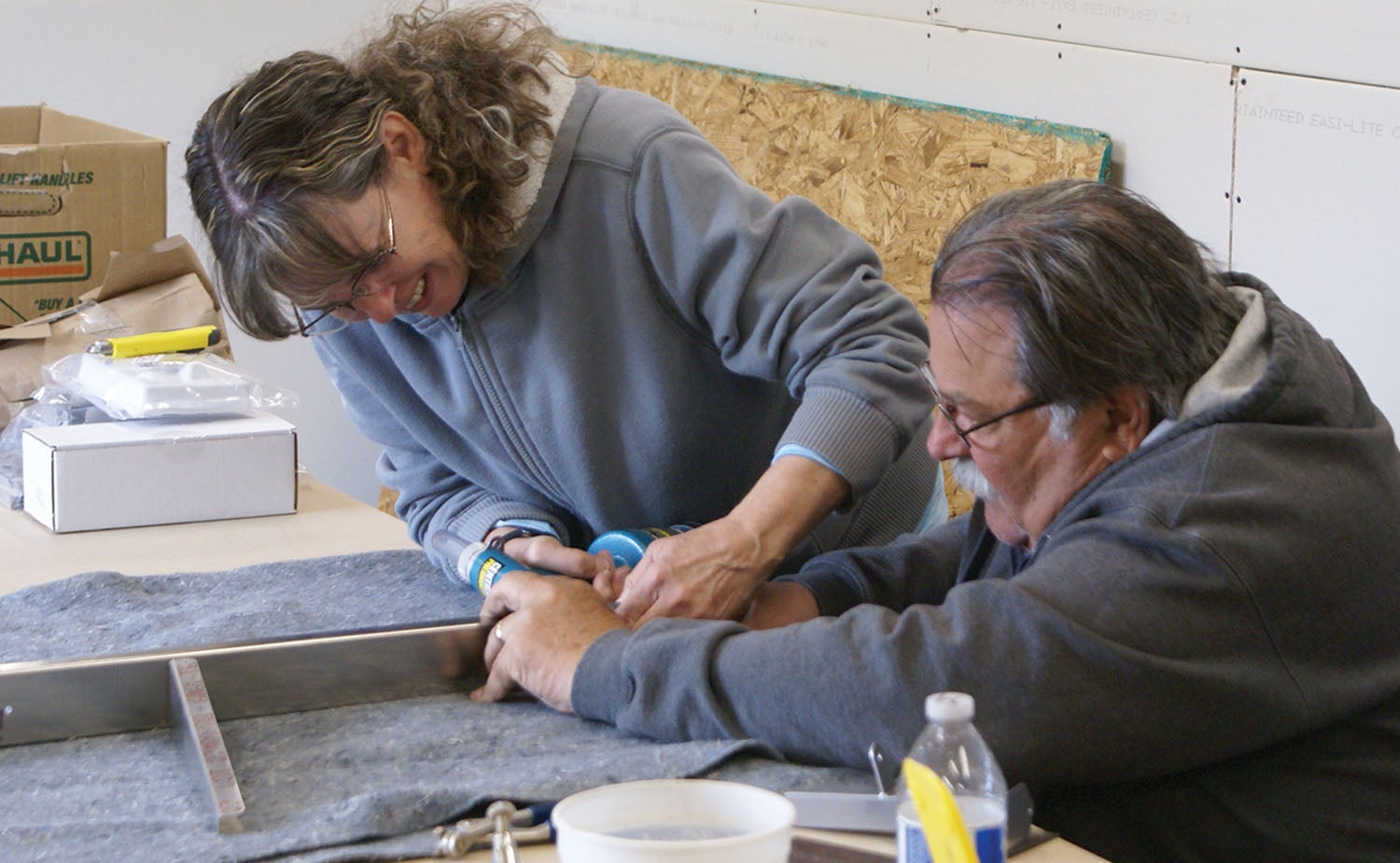
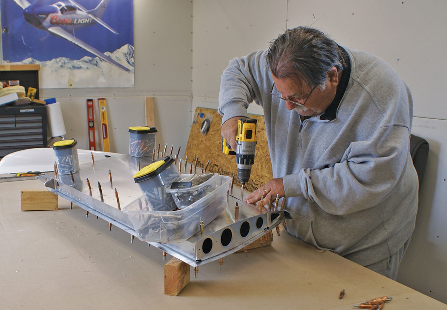
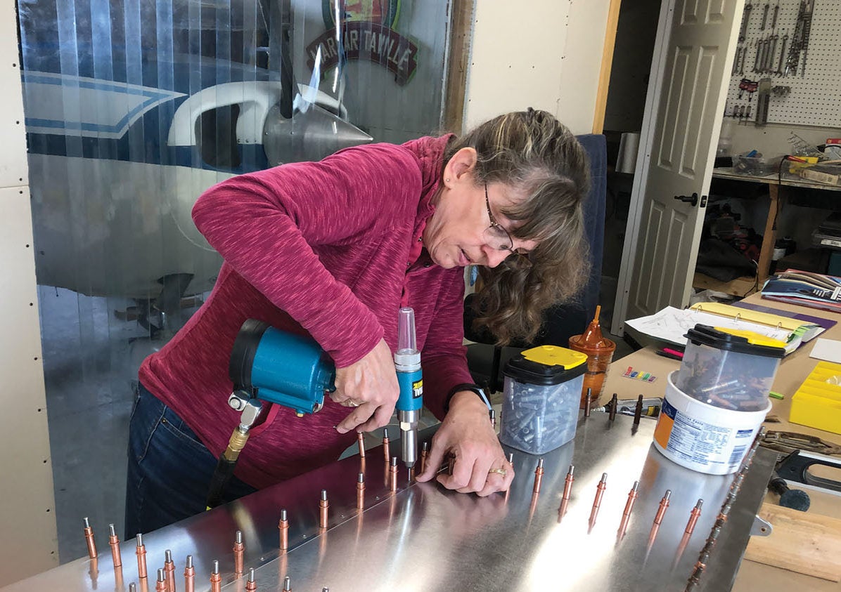
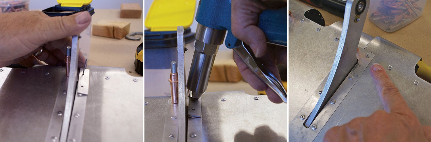
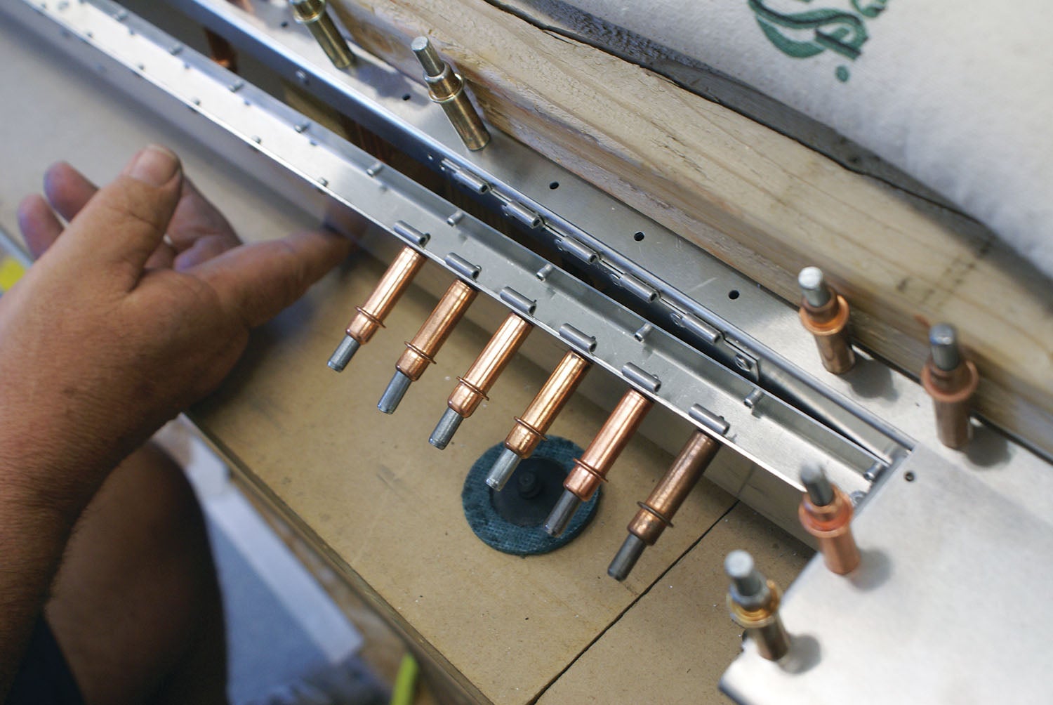
We started with the rudder frame assembly, where I got to pull my first rivet with the pneumatic gun. It was very exciting! (Remember that the S-21 is predominantly a pull-rivet airplane rather than using conventional driven rivets.) Like most metal aircraft, you start with the skeleton before you put on the skin, which seemed very logical for the nurse in me. Mike and I worked well together taking stickers off, deburring as needed and Clecoing the pieces together.
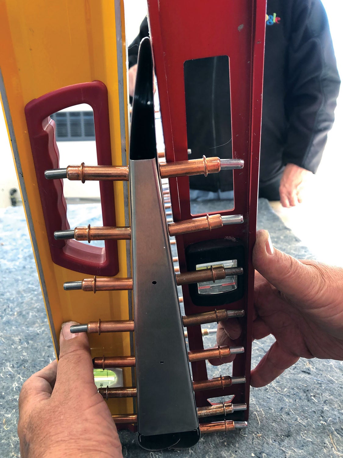
Clecoes are a builder’s best friend, as I was soon to learn. And it’s true that you almost can’t have too many of them. Because they’re durable, they’re a worthy investment in tools.
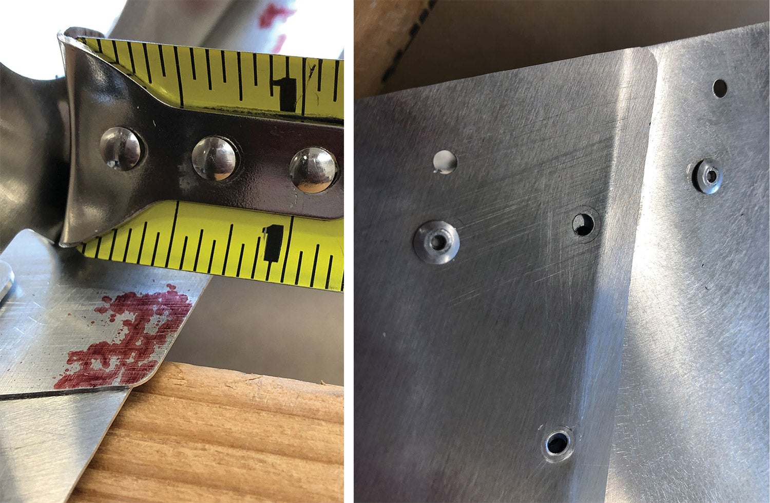
When we Clecoed the rudder skin to the assembled frame, however, Mike said, “We have a problem.” Not words I really wanted to hear! He held up the rudder and you could see a bend on the trailing edge. A neighbor, who happens to have been a designer by trade, was visiting at the time, and the three of us soon came to the conclusion that the rudder skin itself had been bent by the factory in the wrong place. The three of us documented the bend, and we called it a day, frustrated.
The Wrong Part?
That night I kept mulling the issue over. I remembered reading on a “RANS Clan” post, “If you think the part is wrong, check again because most likely you’re the one wrong.” The following day, Mike and I removed the Clecoes from the skin and verified that the holes did not match up properly, so there was definitely a problem with the part. It happened to be Sun ’n Fun week in Florida and the majority of the RANS staff was there. Mike called the factory and was able to talk to Eddie Gil, the builder we met when we toured the factory, and he said that they had a problem with some of the rudder skins not getting folded properly. He apologized and promised to get another in the mail to us. While it was frustrating to get started with a defective part, I was so happy that issue was resolved with the factory so easily! Kudos once again to the RANS folks for coming through!
As we waited for the rudder skin, we started on the vertical stabilizer. Being the process-oriented individual that I am, it bothered me that we were jumping to another assembly before having the first one done! I just tried to go with the flow.
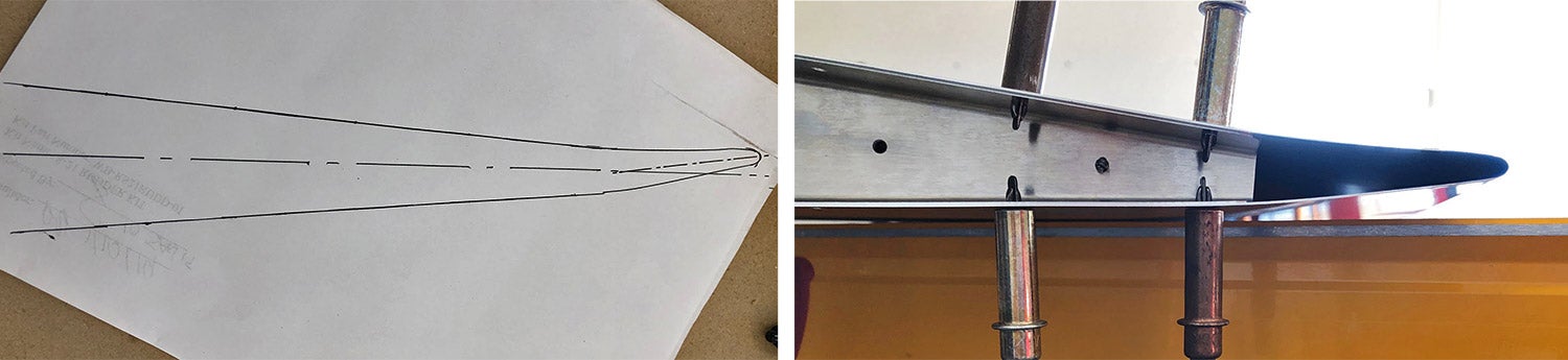
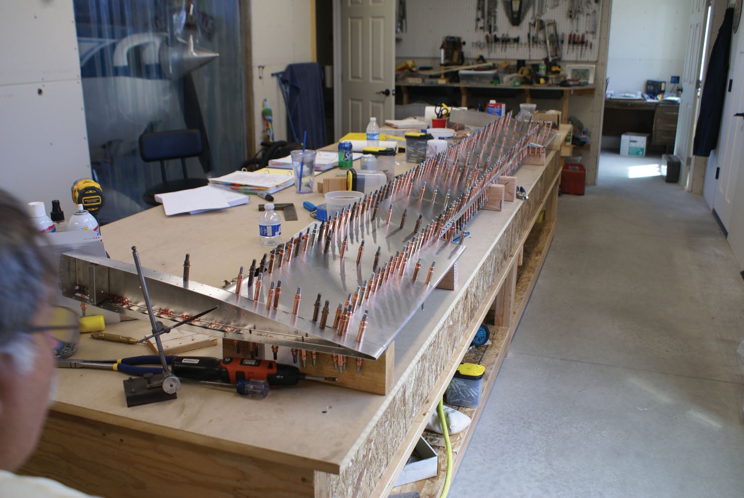
One very important part of the prep work to building is having a straight frame. Mike was magic with the fluting pliers, working carefully to get the ribs to lay flat. With the frame now riveted and level, it was time to get the skins on. Side skins were Clecoed onto the frame and transfer-drilled to the spar with the holes on the leading edge skin as the guide for drilling. I inserted Clecoes as Mike drilled, and got both left and right side skins drilled and assembled. Leveling was checked several times and all looked good. We riveted the left-side skin and went to rivet the right side and noticed a great twist.
How could this have happened? I was mystified and confused. We checked for level several times along the way while we had it Clecoed together. But we didn’t pick up on the twist until after one side had been riveted. We had our builder neighbors, Paul and Louise, come over for a visit to discuss our situation. Immediately when Louise saw our work, she put her finger on a spot where the left skin was offset 1/8 inch from the leading-edge skin where the transfer drilling had taken place. I could not believe that such a tiny amount of offset could be causing this huge twist. But Paul and Louise pointed out that a tiny mismatch like that amplifies itself through the entire part and can cause this much of a twist. That was so hard for me to believe!
Dreaming of Metal
I had another night of dreaming about a twisted vertical stabilizer. I know it sounds crazy, but this stuff can really get to you. Since it was the weekend, we had time to think about our options. We could either see if we could repair the skin(s) or replace them. We had to do more analysis on it to try to exactly identify why it was off. Mike and I both came to the conclusion that we needed to remove the rivets from where the left side skin met up with the leading edge skin on the spar—where the transfer drilling had taken place—to see what would happened to the twist. When we removed the final rivet that was in the spar connecting the two skins, it seemed to have a lot of tension on it, and when it was drilled out the skins relaxed into place and met up, even as could be! It was flat and the right skin was fine. We had found the culprit—exactly as Louise had identified. The holes on the left side skin where it had been transfer-drilled to the spar were mismatched and we decided that replacing left skin was our option. We photographed our issue and sent it to RANS on Monday requesting a new stabilizer skin and more rivets.
The explanation was actually quite simple. Mike and I had been incorrect in the way we were checking for level. We did not fully understand the directions. The manual tells you to measure off a Cleco in the end rib, and that made no sense to us. Mike had been checking for level by measuring the height of the leading-edge skin instead, but had to estimate the exact center of the curved section.
We finally figured out what they meant! There are tiny holes in the web of each end rib for this purpose, but we thought they were talking about the rivet holes in the flange of the rib. Now we figured out that mystery!
Going forward, Mike used one of his cool tools, a Starrett machinist height gauge, that could pinpoint an exact height off the Cleco in the end rib to precisely check the part for straight and level. Paul also had a helpful hint that the best way to transfer-drill a piece of metal like this is to use a few Cleco clamps on the skins, start at one edge that is matched up and then drill from that end first. That way it sets the metal in the correct position and you can Cleco as you drill. Mike used Cleco clamps, but had started drilling in the middle of the piece. I noticed that it didn’t exactly match up when we were doing it, but didn’t think anything of it because it was “so close.”
Lessons Learned
Here we were. The first two parts that we started on our build ended up needing to be replaced. And that’s not a great feeling! We talked to Shelly at the factory after they returned from Lakeland, slightly delayed due to weather, hoping to get both pieces sent in the same shipment. But the RANS staff at the factory was so efficient that the replacement rudder skin had already been shipped, so this replacement piece would be a separate shipment. We also could see that we were going to need more rivets, so we ordered some extras. One thing I learned is that not every rivet is perfect (builder error) when pulled, thus some spare rivets for errant pulling are a must.

I was getting frustrated, so I took the day off while Mike forged ahead. His next task was the frame assembly of the horizontal stabilizer. This gave me time to reflect on where I was at with the build. Being the process-oriented person that I am and having had a third meltdown for “doing things out of order,” I had to come to grips with the reality of building your own plane. Yes, it’s that second-favorite phrase: things happen!
This is a fundamental truth of homebuilding. You may not know what’s around the corner or what your next obstacle is going to be, but there will be one! Deal with it. I had to understand that the manual is not written like a book—with a beginning, middle and end. And not all the steps are laid out in exact order. I suppose I was expecting to build smoothly from one step to another. But those of you who have built before know this as well as anyone—there’s nothing linear in airplane building. I finally had to learn that when you meet a roadblock, you don’t stop. You figure out a way around it and find something else to work on. This one was a tough one for me, but I was much better off when I realized this was the way it was going to be.
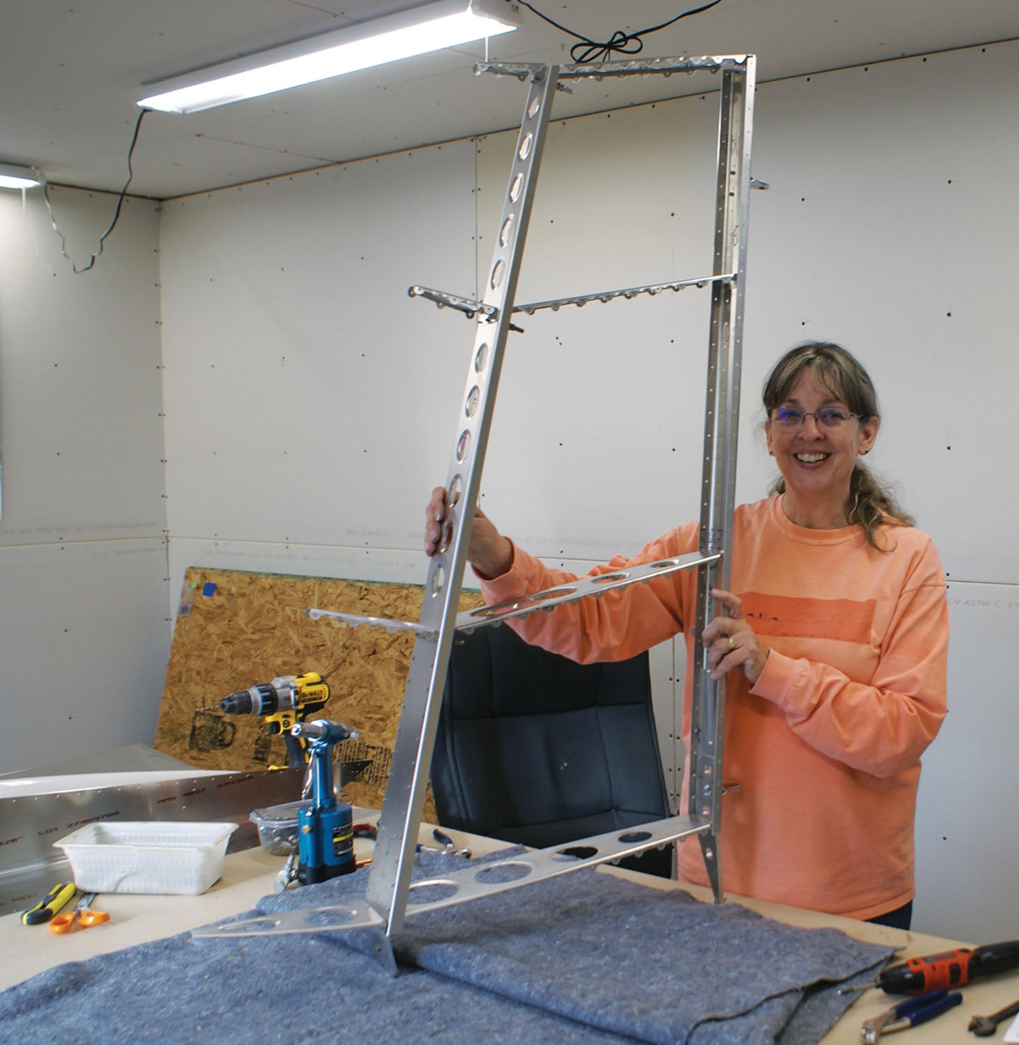
Back to the Stab

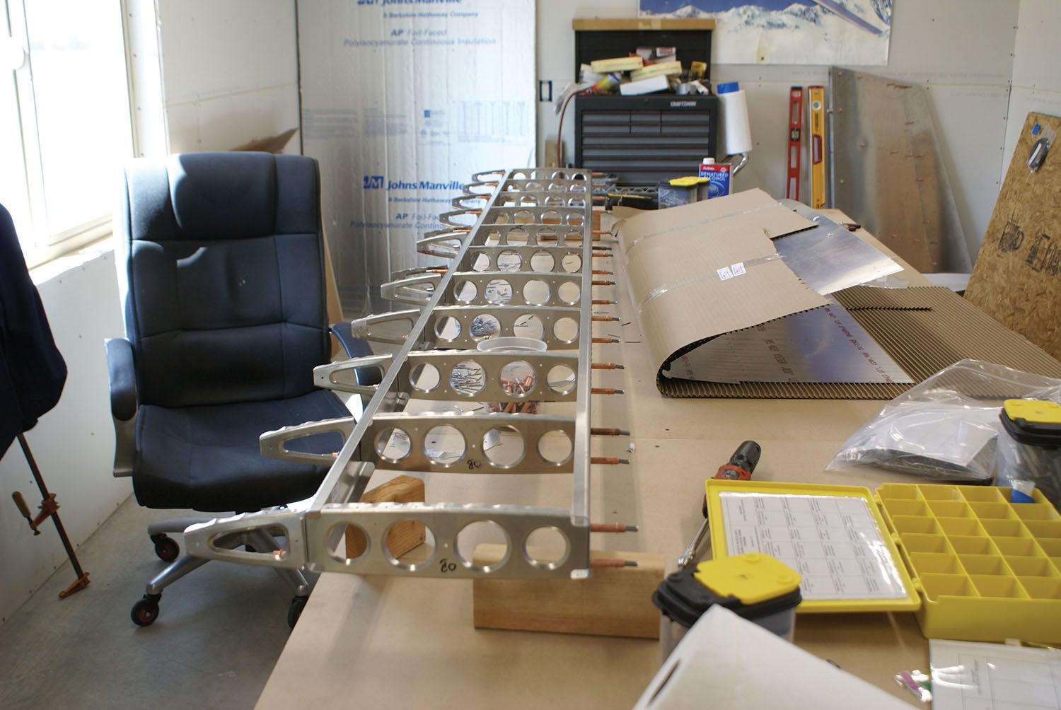
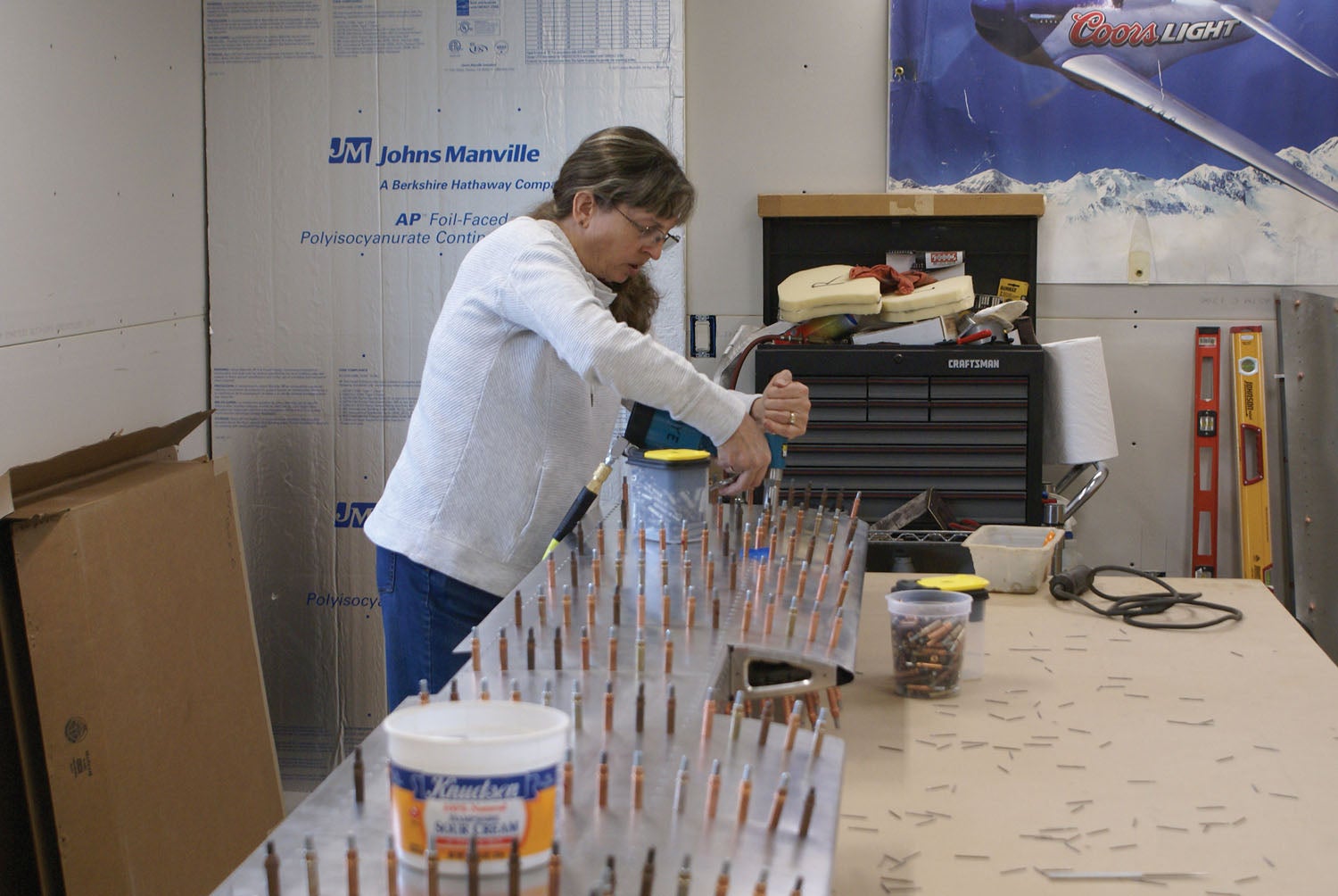
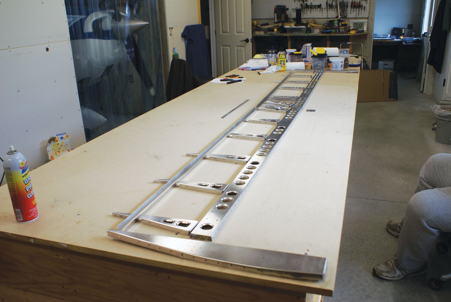
The horizontal stabilizer is huge in comparison with the rudder and vertical stabilizer! Mike had the frame assembled, and now it was time to move on to the skin. Mike up-drilled some holes that needed to be bigger, while I followed with the Cleco, un-Cleco, deburr, re-Cleco, and level, level, level. Finally, riveting. I was also just learning that the repetitive nature of this work is just that—very repetitive. Not only that, it takes longer than you think it should if you want it done right.
Another finishing step I learned is that I like to have smooth rivets—Any mandrels sticking out and sharp are not acceptable, so I marked any rivet that was sharp and sanded down the mandrel so the “final product” had no sharp edges. DNA samples from your own flesh are going to happen during the build, but try to minimize them if possible. Flip it, check for level and rivet the other side.
I learned early on that I loved to do the riveting because it gives me great satisfaction to pull a nice rivet! I even got to the point that one type of rivet became my favorite, because it was pretty, which made me wonder if, even at this early stage, I had already been doing it too long! We got the horizontal stabilizer done and what a great sense of satisfaction! It was level, no twisting and looked really nice! The feeling of satisfaction that comes with successfully completing a part had finally been established!
Return to the Scene of the Crime
While completing the horizontal stabilizer, we received the replacement skins for the rudder and vertical stabilizer. We decided to work on these pieces before taking on the elevator. We were really relieved to see the rudder skin holes match up evenly where the fold was, and once Clecoed onto the frame it looked perfect! In fact, it fit like a glove—what a relief! With renewed confidence, we did the magic cycle of Cleco, un-Cleco, deburr, Cleco, rivet, flip and repeat—checking for level frequently, of course. Soon enough, the rudder was done. Such a relief.
It was on to the vertical stabilizer next. It’s unnerving to redo a part that you know you messed up the first time, but at least we understood where we thought the error had been and could forge ahead with the task! We had to drill out all the rivets on the old skin, remove it and replace it with the new skin. We Clecoed it all up, leveled it and, according to the directions, this time based on the holes in the end rib web, began transfer-drilling at one end with the Cleco clamps in place. After that, we tacked it down at one end on the forward spar, drilling with the metal perfectly aligned and working toward the middle, then followed the standard practice of locating a Cleco every other space as we pulled rivets. It worked beautifully, plus there was no twist. What a relief to have these pieces behind us!
Next up, the elevator and trim tab. This was the most involved part encountered on the build so far. Mike read the manuals trying to understand how it was all to come together and seemed to have a good grasp on it, though I was puzzled in a few places. For example, Clecoing the leading edge of the elevator skins to a piece of PVC pipe to make the metal curve in just the right way…well, that seemed pretty bizarre to me! By now we’d begun to trust RANS even more, so we followed the instructions to the letter. And what do you know: They actually turned out great!
The trim tab itself was not too hard to assemble, but the tweaking involved with getting the hinges mounted on the trim tab and the aft part of the elevator were quite the trick for Mike. Colorful expletives from him filled the room.
Up to this point, we had been working with relatively small parts. With the elevator, I learned that it takes more time than I thought to get this large of a piece done. I also learned that not 100% of your rivets are going to be perfect. Some will need to be drilled out and done again.
I learned another lesson about riveting, one which I will not soon forget. I came to a “tight spot” on the bottom skin near the elevator horn that the tip of the rivet gun would not fit. What the heck was I going to do about this?
When I asked Mike, he just smiled and went and got his pliers and this little aluminum wedge with holes drilled in it. He bent the stem of my rivet, placed it in the hole near the horn with the mandrel bent away from the work, put the aluminum wedge over the stem and said, “Pull it.” My first thought was, “That’s not going to work.” But I decided to trust Mike on this one, so I put the rivet gun snugly down on it, pulled the trigger and, like magic, it worked. I was so excited—just like a little girl, jumping up and down laughing! I thought I was sunk and here he had such an easy answer to my dilemma.
With the finishing touches to the elevator, we had just completed our final part of the tail section. This was much more of an emotional roller coaster than I ever anticipated it would be. We’d experienced failures and been baffled. But we also had many wonderful hours of working side by side, brewing conflicts and crafting resolutions—then sharing our sheer joy over the victories. Maybe building an airplane is only part of the point.


Laura ,
I came to your article because I’m interested in building RANS S-21 as my very first build.
What I didn’t expect and found valuable was your honesty and insight about the build process. Your frustration and fundamental truth of building put into perspective the psychological aspects of building. It was great to read. Thanks for sharing.
Comments are closed.