So, you’ve got your pretty airplane all fitted out with antennas. In metal ships, you’ve bolted them to the exterior of the airframe* and in plastic ships you’ve put them into the foam. How do you test them to be sure that they work properly? And even more important in the case of plastic, how do you test them before you glass them over for all eternity?
Simple—you use a VSWR (pronounced VIZZ-war) meter. End of column. Well… maybe not.
VSWR is an acronym for Voltage Standing Wave Ratio. That’s a highfalutin term that asks how well your antenna is matched to the coax cable and input/output impedance of your radio. Some people use the proper term VSWR. Some use the slang SWR (swurr). Same, same.
It’s sort of like your engine that has the mount, the ignition, the prop, and everything else that shakes “tuned” to one specific engine RPM (frequency, if you will) to eliminate—or at least reduce—vibra-tion to a minimum. At frequencies (RPMs) removed from this tuning, the engine starts to vibrate a bit, and then a bit more, and finally when you get down to idle, that engine is shaking around like a wet puppy. And what is all that shaking around doing? Simply wasting power because it isn’t tuned to the right frequency of those pistons slapping themselves silly.
Immediately we see some parallels. First of all, the engine/antenna is only perfect at one particular frequency. Second, as we get further and further away from the perfect frequency, the engine/antenna starts to deliver less power to the propeller/antenna and wastes more in shaking around. We can change the center frequency as we wish, but the further we depart from the center frequency the more power is wasted, and in the electronic world, we can only waste power in heat.
Now I’m going to totally confuse you. I’m going to talk about antenna impedance, and it’s most unfortunate that the electronic world has raised a royal confusion by measuring impedance in ohms. (I tried getting them to measure impedance in weirs, but it was no-go. After all, with one volt and one ohm in the circuit, w=eir.) For most of us, ohms are what we measure when we put our ohm meter on a lightbulb and read a certain resistance. And therein lies the rub. Resistance and impedance are only the same thing when we use a battery, or direct current. Once we start putting alternating current into the mix, we have to start measuring impedance—and a plain old ohmmeter won’t do that. We have to use an imped-ance meter of some sort.
An easy example is the speaker in your airplane that is rated as either 4Ω (Ω is the Greek letter “omega” which is the electronic shorthand way of saying ohms) or 8Ω. But measure it with an ohm meter and you will not get 4Ω or 8Ω. That’s because the speaker impedance (measured with an audio impedance meter) is measured at 1000 Hz (Hertz, one complete cycle of the waveform per second), about the frequency that the highest note that an operatic soprano can hit with regularity (o’er the land of the free…). And why this frequency? Because it is about the center of the frequency range of the human ear…300 to 3000 Hz. Same with headphones. Same with antennas, whether they be on insects or airplanes.
Let’s talk about this impedance stuff for a minute, now that we’ve cleared the air about ohms. If we take an impedance meter reading at a dipole antenna (rabbit ears), we find that the impedance at the center frequency, where each arm of the dipole is a quarter-wave long, is about 70 ohms. But if we take that same impedance meter reading at the base of a ground plane, we find that the impedance is about 35 ohms. That sort of stands to reason, in that a ground plane is nothing more than a single monopole (as opposed to a dipole) that uses the ground plane as a mirror to “fool” the monopole into seeing its reflection in the ground plane and thus radiating as though it were half of a dipole. Heuristically, you can almost convince yourself that a monopole should be half the impedance of a dipole. Sort of.
Back in the days “befo da wah” (WW-II), somebody had to standardize on an impedance for radios. Since the dipole people were as adamant about the standard being 70 ohms as the monopole people were adamant about 35 ohms, they came to a compromise in the middle (square root of 70*35 = 49.49; (70*35)/2 = 52) of 50 ohms. And thereby hangs a tale about British plumbing standards that will wait for another day. At any rate, our airplane radios expect to work from or into a 50-ohm impedance.
This, of course, makes an instant mismatch no matter whether you use a dipole or a ground plane. The mismatch in a 50Ω system is a VSWR (which we know nothing about just yet) of about 1.4:1 (remember the R in VSWR is ratio), which might be something to worry about. Not just yet. We’ve got some more important stuff to do.
So, not to get ahead of ourselves for next month’s column (and what VSWR really does to us), we can look at the little Romex Ranger ground plane we made last month as an example.
Remember that we made the Ranger out of #14 copper house wire? There is a wonderful antenna design program called EZNEC by a pretty savvy engineer named Roy Lewallen, who is also a crackerjack amateur radio sleuth (W7EL) in Oregon. Roy sells the program, but also offers it for free for simple antennas. A ground plane is as simple as it gets. If you want to play with designing your own antenna, download the program from www.eznec.com.
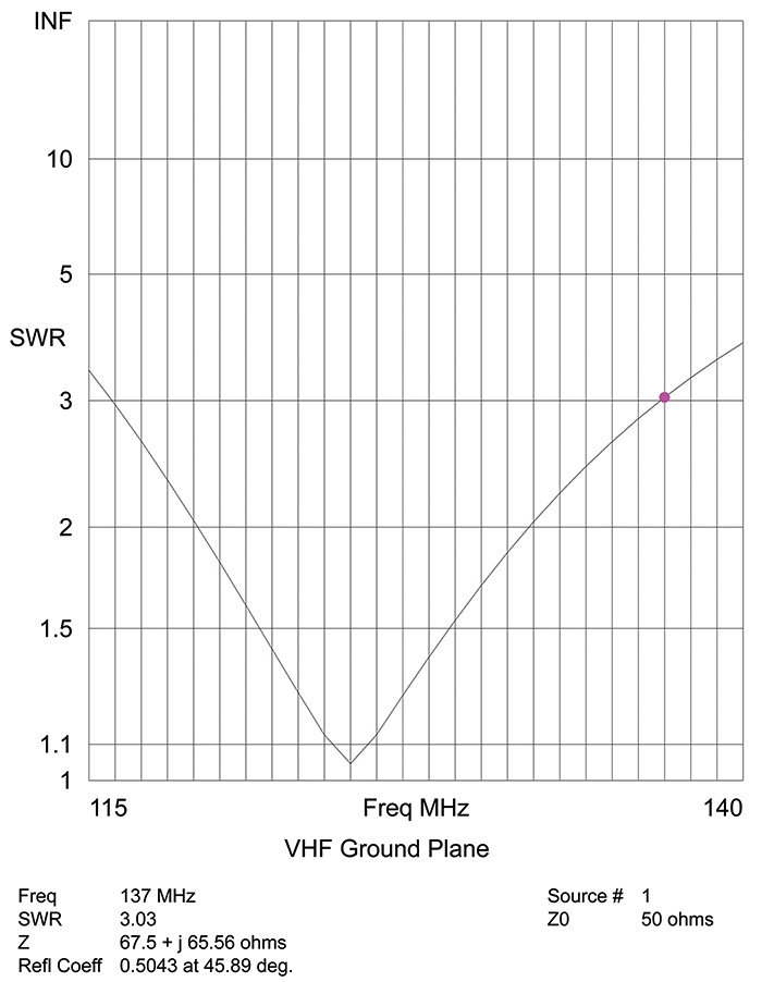
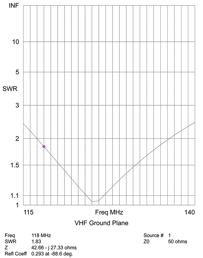
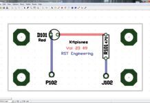
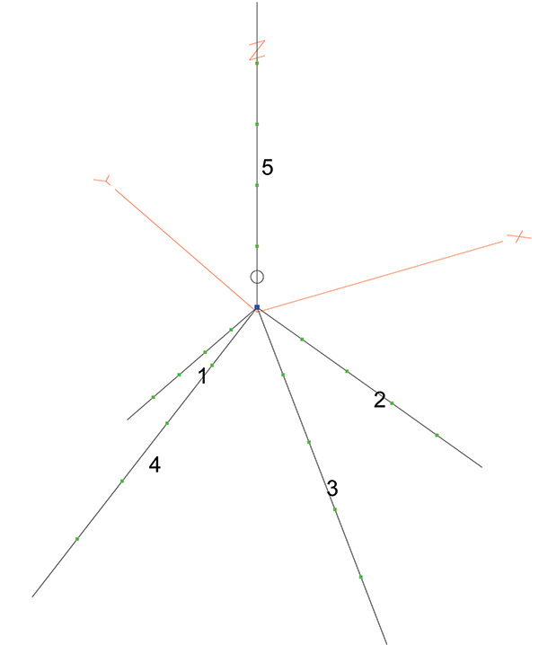
At any rate, Figure 1 shows the construction of the antenna from wires 1-4 (the ground plane) and wire 5 as the radiating element. Figures 2 and 3 show the “goodness” (VSWR) factor of the antenna from 118 to 137 MHz (the aircraft COM band). Note the low VSWR at the center frequency (1.045:1), but at the band edges, it goes from 2.31 at the low end to 3.03 at the high end. This is not a very broadband antenna, but it will certainly work at the center frequency and a few MHz (MegaHertz) to either side. If we accept 2.0 as the VSWR limit, this antenna is good (a purely subjective term) from 119 to 132 MHz.
So while this simple antenna is a good, compact design for fly-ins, what do we demand when we go to use this sort of thing on airplanes?
Let’s do one simple thing and I’ll bet you get the idea. Instead of thin #14 copper, let’s use thick half-inch wide copper tape for the elements. Now look at the difference (Figures 4 and 5). Instead of a very sharp point at the bottom, the point has changed into a valley and the band edges have gone from 1.83 on the low end to 2.08 on the high end, and all we did was change from thin wire to thick tape. And the heck of it is, it doesn’t matter if the tape is super-thin (and lightweight); the only criteria for VSWR is the widest part of the elements.
Now some more stuff for next month: How do I measure VSWR? Why the droop of the ground plane elements at a 45° angle? What does the antenna look like at a distance? What does a dipole look like made this way? How fat is fat? Will Timmy save Lassie from the wolf? Stay tuned.


