Photo 1: Ballenger air/fuel monitor components. Clockwise from upper left: wiring harness, processing and display unit, instruction manual, weld-in bung, NTK oxygen sensor, and bung plug (for operation without a sensor).
Direct measurement of air/fuel ratios (the mass ratio of air to fuel) has been used as the gold standard method for optimizing engine performance in auto racing for years. Yet, while we refer to mixture controls and leaning in the operation of our aircraft powerplants, we don’t really know the actual mixture directly and typically perform adjustments using exhaust gas temperature as a proxy for A/F ratios. Dave Hirschman recently wrote a great introductory article (“Lean on Me,” AOPA Pilot, February 2018) extolling the virtues of A/F ratio monitoring in airplanes. Our goal here is to go into more detail on A/F ratio monitoring theory, describe a complete installation, and review results and operational data, hopefully enabling other homebuilders to make their own installations.
Background
The automobile industry, motivated by pollution standards, began using catalytic converters back in 1975. That created the need for a method to directly measure A/F ratios in cars, first to optimize catalytic converter effectiveness, and then to minimize emissions and optimize fuel economy and enable closed loop operation with electronic fuel injection. Around 1990, an automobile application-compatible (read cost effective) oxygen sensor was introduced by Bosch, and that technology persists to this day as a key component of efficient and minimally polluting internal combustion powered vehicles. An additional side effect that we will discuss later with respect to aircraft engine operation was the need to eliminate lead in gasoline, since lead will foul catalytic converters and degrade the oxygen sensor’s performance.
Air/Fuel Ratio Theory and Aircraft Engine Operations
As pilots, we’re already familiar with the concept of A/F ratios from our use of mixture controls in the process of leaning. And you may already know that the optimum mass ratio is 14.7 to 1, meaning that for every pound of gasoline to be burned completely, 14.7 pounds of air are required to supply the exact number of oxygen molecules needed for complete combustion of the gasoline. In chemistry terms, this is known as the stoichiometric mixture. A ratio of less than 14.7 results in a rich mixture with excess gasoline, while a ratio greater than 14.7 is a lean mixture with excess oxygen.
Typically, operation at the stoichiometric mixture will result in peak exhaust gas temperatures (see Figure 1). Peak CHTs typically occur around -30 to -50 degrees EGT rich of peak, and peak power at -100 to -120 degrees EGT rich of peak. With our air-cooled aircraft engines, continuous operation at maximum power and stoichiometric mixture will result in damaging temperatures and internal pressures, so we take off and climb with rich mixtures where excess fuel provides necessary cooling and protection against detonation, and cruise rich of peak if operating at 75% power, and either lean or rich of peak when operating below 75% power, whatever your persuasion.
The efficacy and risks of operating lean of peak continue to be a matter of great debate. On the lean-of-peak advocate side are John Deakin’s very informative AVweb “Pelican’s Perch” articles on engine operation1, and of course the folks from GAMI. On the other hand, both Lycoming2 and Continental3 for the most part advocate best power rich of peak operation and very careful, well-instrumented lean-of-peak operation for maximum range, if you must! In fact, most Lycoming engine operation manuals recommend economy cruise at less than 75% power at peak EGT4,5.
Except for knowing where the peak is, EGT in and of itself is a relatively meaningless number. The peak temperature also varies with power settings and other factors, so repetitive mixture setting requires repetitive finding of the peak EGT. Our goal with A/F ratio monitoring is to get away from the use of EGT as a proxy for A/F ratio and be able to set mixture directly and predictably.
A/F Monitors and Aviation Suitability
Oxygen sensors for cars need to monitor the mixture ratio in only a narrow region, just either side of stoichiometric, and as such are classified as narrow band. For aircraft the oxygen sensor must be able to measure the mixture over a much broader range, which requires a somewhat different wideband sensor technology. Such devices are made by Bosch and NTK. In the past, these sensors were easily fouled by the lead content of fuel, rendering them unsuitable for avgas use, but recent designs are more tolerant. The NTK sensor is noted as particularly more tolerant of leaded fuel. Monitors are available from several companies, targeting primarily the auto racing community. One popular model is the AEM Electronics X series, which uses the Bosch LSU 4.2 sensor. Another is the Ballenger Motorsports AFR500v2, which can use either the Bosch or NGK/NTK Wideband O2 Sensor, the latter of which has the reputation of being far more tolerant of leaded fuel and is therefore the unit I chose. Further, it has a rectangular display, which is an easier fit with my panel than the round displays typical with most other units.
Installation
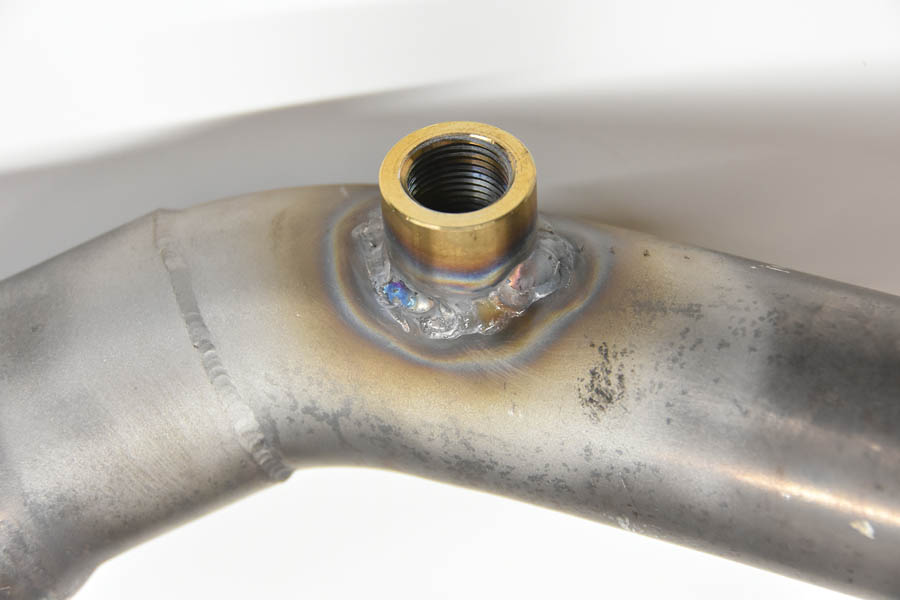
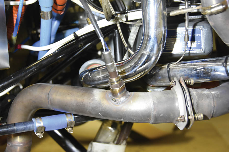
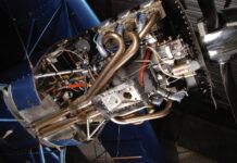
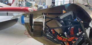
Photo 1 shows the components of the Ballenger AFR500v2 kit, consisting of the display unit, sensor, interconnect cable, and sensor installation bung. The latter needs to be welded into an exhaust pipe, recommended between 1 and 4 feet from an exhaust port. Given that the cylinders may peak in EGT at different mixture settings, a decision needs to be made as to what is the best place to locate the sensor. Mine is a two-into-one dual exhaust system, combining cylinders 1 and 3 on the right, and 2 and 4 on the left. Cylinders 1, 3, and 4 peak at nearly the same mixture, while cylinder 2 peaks about 0.5 gallon per hour earlier. I chose to mount the sensor on the cylinder 1 and 3 side. The sensor mounting bung is stainless steel, and Photo 2 shows it welded into the right exhaust pipe. Photo 3 shows the pipe installed with the oxygen sensor.
The controller/display was initially mounted temporarily on top of the glareshield while performing test runs and establishing the long-term viability of the system. The cable connecting the display unit and sensor needs to go through the firewall. Aware of such a possibility, Ballenger provides instructions on how to disassemble the cable connector to allow slimming the assembly down to facilitate the firewall penetration.
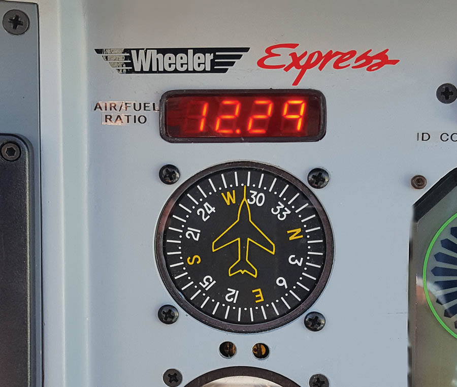
The construction of the Ballenger AFR500v2 A/F ratio monitor is excellent. However, the size of the display is substantially larger than the panel real estate I wanted to dedicate to this function and does not include any dimming. Despite Ballenger’s admonition not to open or modify the control module, the electrical engineer in me could not resist changing it to an external smaller and auto-dimming display. Photo 4 shows the final installation.
Photo 4: The finished installation. The air/fuel ratio display is mounted near the top of the panel, above the magnetic compass.
Test Flights and Results
Once installed, I chose to perform two test flights, the first at 3000 feet, the second at 6500 feet. For my Lycoming I/O-390 and Hartzell prop combination, 75% power is at 2500 rpm and 24.6 inches manifold pressure. Since Lycoming recommends running lean of peak only at powers less than 75%, the 3000-foot test was conducted at about 65%, corresponding to 23.5 inches manifold pressure. Figure 1 shows the well-known Lycoming graph of power, CHT, and EGT versus fuel flow. Peak EGT corresponds to a stoichiometric mixture, and as the mixture leans from the rich side, CHTs peak just slightly ahead of the peak EGT.
Figure 2: EGT, A/F ratio, and mpg versus fuel flow at 3000 feet, 2500 rpm, and 23.5 inches manifold pressure.
Figure 2 shows the test results of EGT, A/F ratio, and mpg versus fuel flow at 3000 feet, 2500 rpm, and 23.5 inches manifold pressure. Figure 3 shows the same data for the test at 6500 feet and 23.4 inches manifold pressure. Figures 4 and 5 show EGT and airspeed versus A/F ratio and fuel flow, at both 3000 feet and 6500 feet. The first thing to note is how the peak EGT in fact occurs pretty much right at an A/F ratio of 14.7. How wonderful, reality is matching theory! And, the A/F sensor is working properly. Next, “gas mileage” increases uniformly with leaning. Airspeed increases and decreases in proportion to power, as expected.
Figure 3: EGT, A/F ratio, and mpg versus fuel flow at 6500 feet, 2500 rpm, and 23.4 inches manifold pressure.
Just for reference, since the 3000-foot tests were done at 65% power with a best speed of 179 mph, the 75% power speed is about 185 mph. At 6500 feet, the best speed is about 189 mph.
Figure 4: EGT and airspeed versus A/F ratio at 3000 feet, 2500 rpm, and 23.5 inches manifold pressure and 6500 feet, 2500 rpm, and 23.4 inches manifold pressure.
Figure 5: EGT and airspeed versus fuel flow at 3000 feet, 2500 rpm, and 23.5 inches manifold pressure and 6500 feet, 2500 rpm, and 23.4 inches manifold pressure.
Putting A/F Ratio to Use
OK, so what can we now do with this data and what good is it? Well, going back to the time-honored method of leaning, it consists of momentarily leaning to peak EGT and then adjusting the mixture to an EGT offset from the peak by a predetermined number of degrees. That number is either manufacturer recommended or chosen by the operator according to their judgment of a safe and desirable operating point. The indirect and desired result is a specific and consistent air/fuel ratio.
This is where having a direct indication of A/F ratio comes in as a great simplifier of the cruise mixture setting process. Simply make a single run to determine and note the A/F ratio that results in your desired EGT temperature offset, and in all future flights set mixture to that A/F ratio. Change power setting or altitude and change mixture setting as needed to maintain the desired A/F ratio. It’s as simple as that! Of course, always monitor CHTs—values and trends—and ensure they are in an acceptable range.
For best speed/performance, I typically operate 85 F rich, corresponding to an A/F ratio of about 12.5. For economy cruise, I run about 50 lean of peak with an A/F of about 16.
That said, in researching operational recommendations it became clear to me that there is a lot we as pilots don’t really understand. The second sidebar, “A/F Ratio and Relationship to Detonation, Pre-Ignition, and Safe Operating Conditions,” is an attempt to increase that understanding.
Long Term Performance
Having flown a few weeks with this setup, I really like it. Going forward, the key question is what will be the longevity of the oxygen sensor. Dave Hirschman in his article quotes Klaus Savier, founder of Light Speed Engineering, a California firm that designs and sells electronic ignition systems:
“Lambda gauges take the guesswork out of leaning. Pilots taking off from high-altitude airports can at a glance precisely set the mixture for best power before beginning their takeoff rolls, and pilots leveling off at high altitude in cruise can easily and quickly set the mixture for maximum efficiency. I’ve been flying with lambda gauges in my two airplanes now for a combined 800 hours.”
We shall see!
Three Months Later…
Still going strong! So far the system performance is identical to what it was to start with. Apparently, the new oxygen sensors are indeed tolerant to the small amount of lead in avgas. It’s become a simple and automatic process to set mixture, just as was intended.
References
- John Deakin, “Pelican’s Perch” #43, #63-66
- Lycoming SSP700A, “The ‘New’ Old Leaning Technique“
- Continental “Tips on Engine Care“
- “Leaning Lycoming Engines“
- Lycoming Service Instruction 1094D, “Fuel Mixture Leaning Procedures“
Photos: Reinhard Metz.


