 My Thorp T-18 is a project that one person began and another continued—including the rudder build—before it came to me. Looking over the rudder, I now wonder why the builders before me apparently never considered installing a taillight.
The top of the vertical stabilizer has a fairing that blends into the rudder’s fairing. At the upper end, where the skins come together, the rudder is quite narrow. These features make it hard to install a light without it looking awkward or being blocked. Mounting one at the back of the fairing risks obstruction by the rudder itself. Placing it at the top of the rudder would result in an ungainly extension. I considered adding a light in a small aluminum tube beneath the rudder, but the clearance to the tail spring was minimal—too much risk of contact during a firm landing.

Making It Work Without Cutting
The typical approach is to notch the rudder skins and slide the taillight housing inside. I wasn’t eager to cut into a perfectly good rudder or bolt on a standard bulky taillight. While my LED wingtip lights (which may appear in a future article) provide FAA-compliant rear coverage, I’m still paranoid about someone flying up my tailpipe if those lights are somehow blanked. So, for peace of mind, I wanted a light at the very back of the airplane.
After weighing several options, I settled on an external housing. It’s not ideal, but it avoids reworking the rudder—and in what is already turbulent boundary-layer air, a bit of protrusion isn’t going to matter.
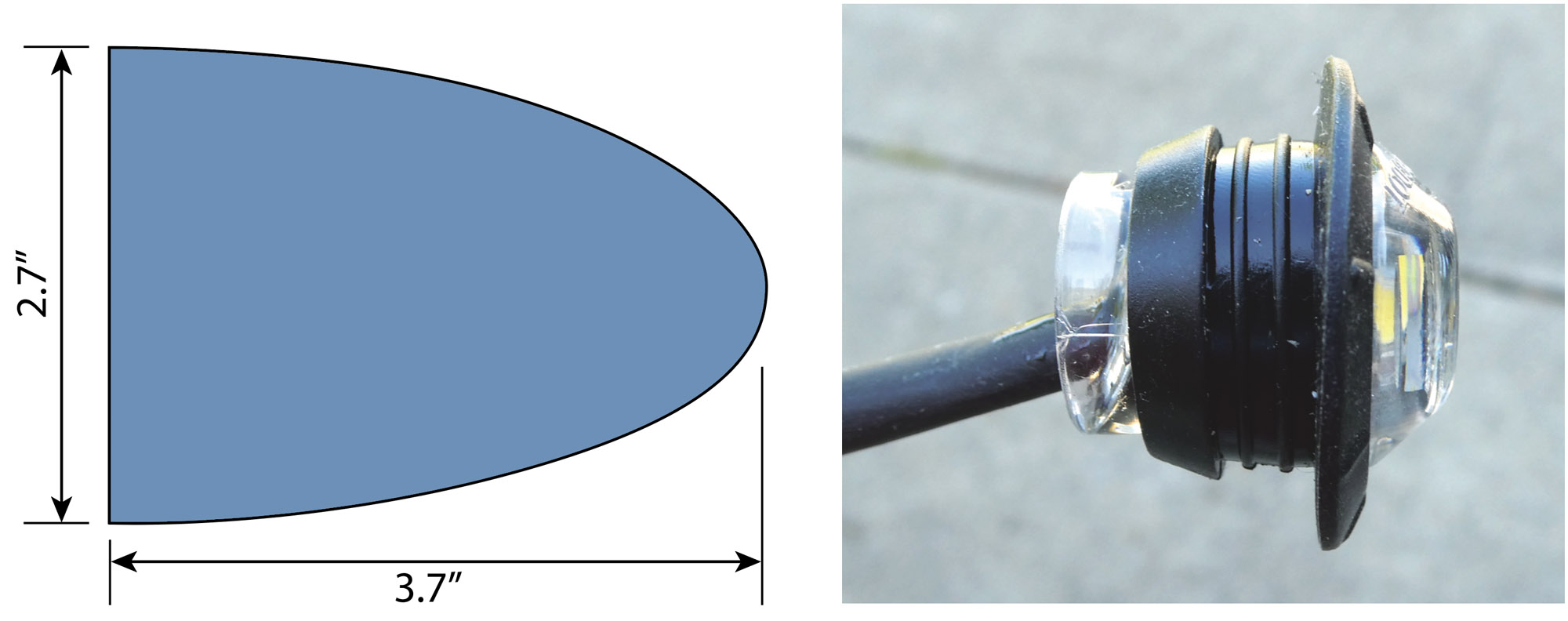
I found an inexpensive, waterproof LED light on Amazon that’s only 3/4 inch in diameter and surprisingly bright. Connected to a flashlight battery, it lit up my backyard—more than enough for a “just-in-case” rear-facing light.
Driveway Engineering
I did this project at home—some of the driveway photos reflect that. Since remarrying, I no longer have access to my full basement workshop. Now, heavy-duty work happens at the hangar on weekends; lighter work takes place at the house during the week.
My first idea was to bore a 0.75-inch hole in a wood block, then slice it to create a trough for hammer-forming aluminum. Lacking tools at home, I started mocking things up with thin cardboard. Then I remembered some leftover aluminum roofing flashing—soft, easy to shape, and perfect for experimenting.
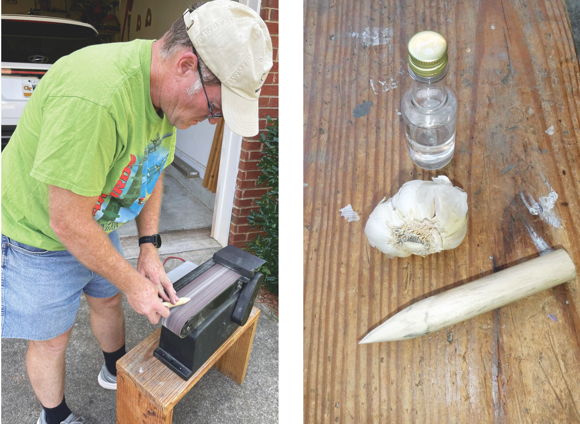
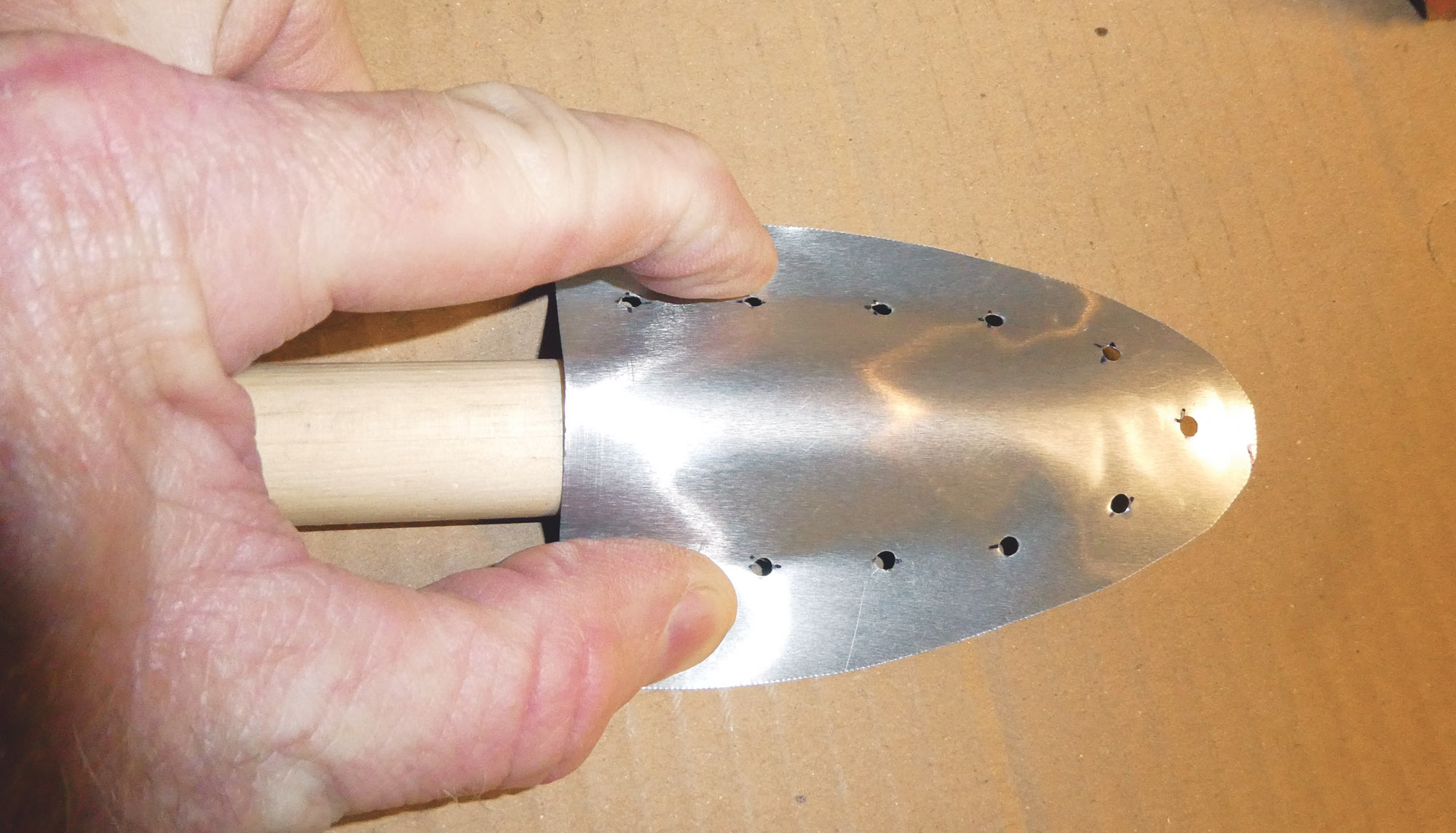
After some initial pressing with a dowel, I realized the metal conformed nicely to shape. Light bulb moment! I used my chop saw to taper a dowel, smoothed it with a belt sander, and cut oversized teardrop-shaped blanks. After clamping the edges to test the fit, I Clecoed the flashing halves together (#40 holes) and inserted the dowel. The housing formed itself.
Assembly and Installation
Originally, I planned to use 3/32-inch blind rivets, but the rivet bucktails lined up and interfered inside the rudder’s trailing edge. So I used tiny #2 screws, clamping the housing halves through the rudder. That let me sneak wiring through the tight corner and clamp the housing around it. The open holes are small enough to be negligible.

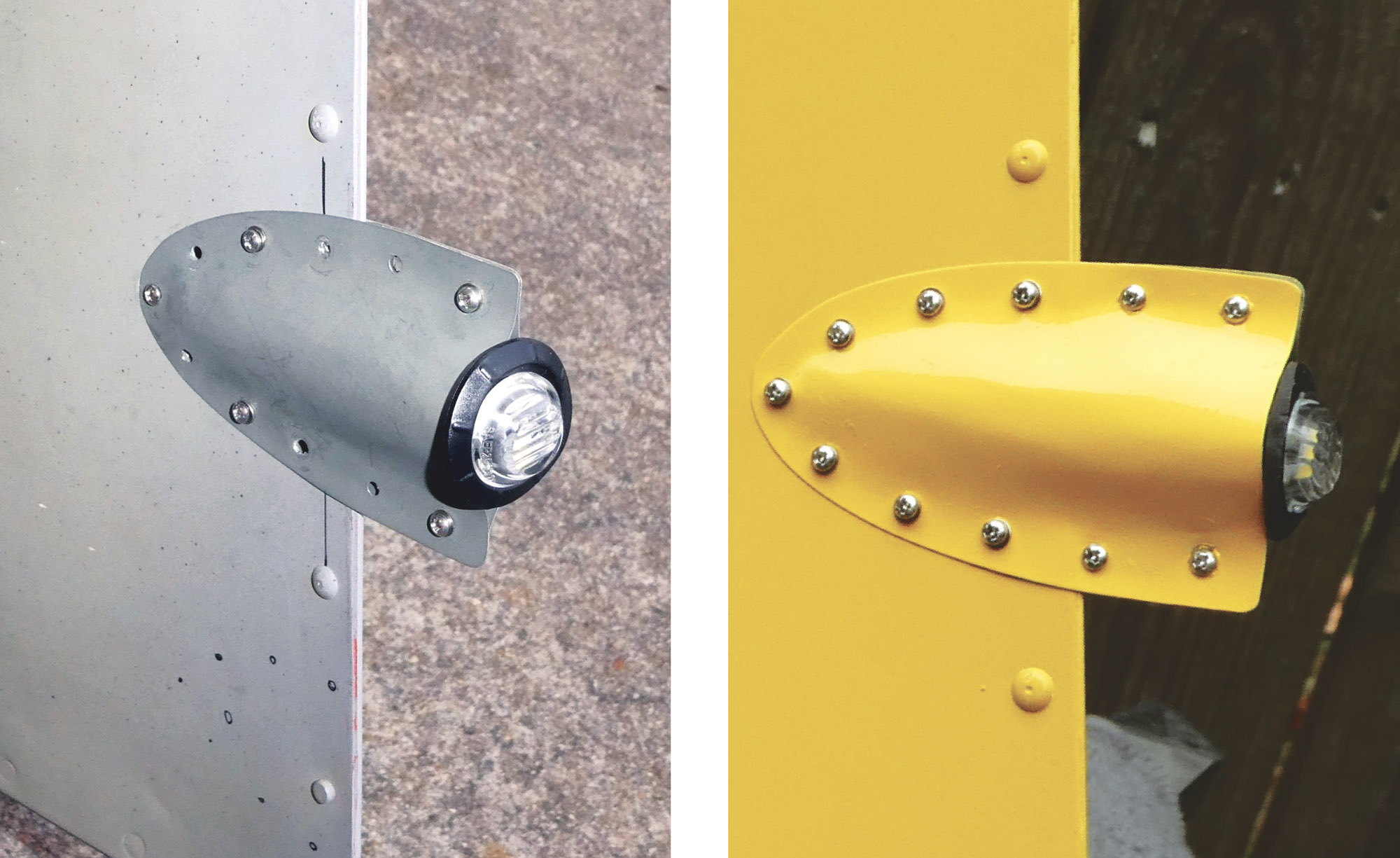
The final result is lightweight, removable, and secure. Between the light’s built-in fluting and the springiness of the housing, it shouldn’t budge. A little RTV will help seal it. Worst case? The light dangles like the world’s smallest refueling drogue—easily spotted on a postflight walkaround.

Trying a Stronger Option
I also tried making one from 0.016-inch 2024-T3 aluminum. It’s tougher to shape but doable. Cut the blanks a little larger to accommodate the larger bend radius. Use a screwdriver to gently spread the halves before inserting the dowel. Once Clecoed, I used duckbill pliers to sharpen the ellipsoidal crease and sanded the edges to final shape.
I then backdrilled the finished housing to the rudder, leaving Clecos in the aft area and sliding the assembly in place over a dowel to preserve its shape. Watch fastener placement—avoid edges or existing rivets. I drilled a 1/4-inch hole for the wire, added a grommet, and routed the wire through the rudder to the aft fuselage. Finally, I trimmed the light flange to match the housing’s shape for less drag and better aesthetics.

Which One?
I’ll stick with the flashing version. It’s virtually weightless and does the job. If needed, I can swap in the 2024-T3 version.
This same process could work for housing a traditional taillight like a uAvionix tailBeacon. In that case, I’d start with a nylon mounting block and larger housing. The best part? A false start costs very little in time or material. Have fun and be a light in the sky.


Great article Andrew see you at Youth program Saturday
My dad’s T18 N455DT appears to have a different style rudder. In ~1970 he mounted his white nav-light just above the fuselage ‘fair’ on the rudder trailing edge…which protruded-out farther than this rudder. John Thorp was concerned about maintaining rudder balance and rudder trailing-edge integrity with a light embedded in the Rudder T.E. He told dad where to place the light on the T.E. and how to re-ballast the rudder [for flutter resistance] towards the hinge-line.
See High quality photo of N455DT empennage… https://www.airhistory.net/photo/734975/N455DT
Comments are closed.