Airplanes are compromises that fly. They give alternate meaning to the idiom “That flies in the face of reason.” Gross weight is compromised for performance. Top speed is compromised for stall speed. Cargo capacity is compromised for weight and balance. The inclusion of machined components is compromised for cost. The list goes on. These compromises can translate into construction detail compromises—not safety compromises—but compromises to what I’ll call “optimal design.”
It’s Not a Problem if It’s Intentional
One design compromise I’ve dealt with as a builder, and while providing builder support, is fastener placement. Fasteners can’t always fall where the rules, symmetry, or “optimal design” would like them—kinda like a wedding dinner seating chart for your dad’s second marriage. (Why didn’t he just elope?) This column focuses on fasteners that encroach on the fillet of an aluminum extrusion or the inside radius of a bent part, preventing it from seating squarely against the surface.
Some may view this condition as a problem or, in the parlance of the day, an “issue,” but most often a hole located close to a fillet or bend is intentional and accommodated by the design. Its location keeps other design elements from becoming expensive, complicated, or heavy. Sometimes, though, the interference is caused by the vagaries inherent in hand-built airplanes, when on-paper perfection doesn’t translate to imperfect human hands. Sometimes, as Sonex Aircraft found many years ago, it’s caused when a material manufacturer increases the radius of an extrusion’s fillet without warning, causing interferences that didn’t previously exist. It’s only a problem if the assembly deviates from what the kit documentation shows, indicating a part or build error, or if one of the following steps can’t correct it.

Cleared for the Option
The three methods I present for creating a flat surface for fasteners near radii are all acceptable, but each has its place, its benefits, and its drawbacks. Before I address each method, let me address edge distance, a concern of some builders who encounter this condition. Edge distance rules of thumb apply to fasteners installed near the edge of a part, where the part can crack and the fastener’s hold can be compromised. A fastener that crowds a fillet or inside bend is not near an edge—it’s near a bend.
Radius Washers
A radius washer is made from an AN washer. One…er, edge(?) is contoured to nest with the fillet, providing a flat surface for a fastener. The benefit of using an AN washer is there is no need to drill a a hole through it it for the fastener. The downsides are it can be difficult to grind the mating radius on a washer, and keeping the radius on the washer engaged with the fillet while installing a nut can be…just as difficult.
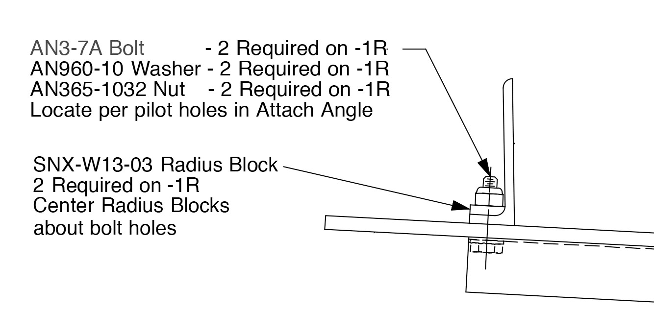
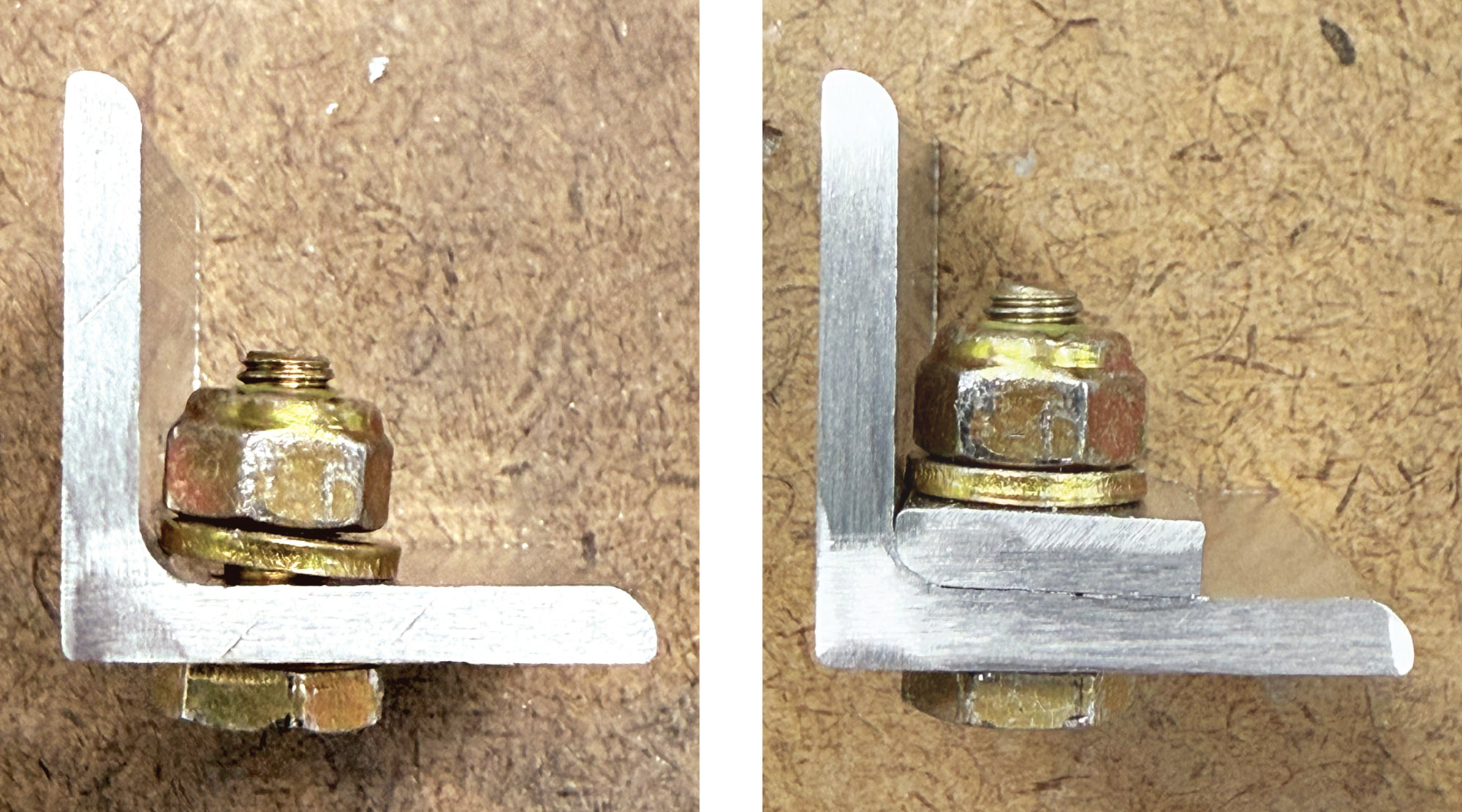
Radius Block
A radius block made from a piece of aluminum whose thickness is equal to the thickness of the part works well, but the ideal material for a radius block is the curved edge of a scrap of the same extrusion that needs the washer. The reason? An extrusion’s edge radius matches its inside fillet, eliminating the need to grind the radius and guaranteeing a perfect fit. The downside to making a radius block is it can be futzy to drill the hole for the fastener.
To drill an accurate hole, the radius block should be match drilled and step drilled together with the hole in the primary structure. When the need for a radius block comes to light after a fastener’s hole has been drilled, drilling the radius block separately is your only option. My method is to clamp the radius block to the part, mark the hole’s location on the radius block with a drill bit equal in diameter to the hole’s size, unclamp the radius block, and step drill the hole to size. If, following this technique, the hole ends up a little off, the radius block can be incrementally modified until the hole is properly positioned. If that doesn’t work, start from scratch making a new radius block.

Spot Facing
Spot facing is a machining technique that smooths/levels an uneven surface around a hole. Whereas radius washers and blocks add material, spot facing removes material. Spot facing can be employed to remove the portion of a fillet that interferes with a fastener. In a well-designed airframe, the small bit of material that is removed shouldn’t compromise a part’s strength. However, before spot facing a part that doesn’t call for it in the kit’s documentation, contact your kit’s tech support staff.

Spot facing is done with inexpensive counterboring tools. Ideally, parts are spot faced on a drill press because it’s tricky to spot face a hole with a handheld drill—the counterbore is asymmetrically loaded when it engages the fillet, which makes it prone to chatter. Use a counterbore whose diameter is equal to or slightly larger than the width of the washer/fastener that will occupy the space and has a pilot equal to the diameter of the hole being spot faced. Reverse counterbores are available for tight spaces, where the body of a drill won’t allow the use of a standard counterbore and the part can’t be clamped on a drill press.
Though spot facing is accomplished with a counterbore tool, spot facing and counterboring differ. Spot facing removes just enough material to level a surface—maybe a smidge more. Counterboring goes below a part’s surface to meet a dimensional requirement or to place a fastener flush with, or below, a part’s surface. Our goal is only to spot face.
While homebuilt aircraft can be the result of many compromises, workmanship should never be one. Each of the methods described here has its pros and cons, and sometimes a particular method is not even an option. Whichever method you may have to employ—and never hesitate to seek the input of the kit’s manufacturer—always do your best work.


That was superb info…thanks!
Comments are closed.