 As all pilots should know, keeping an engine at the proper temperature is important for engine longevity. As Lycoming says in its Key Reprints series of articles:
“Engine operating temperature is another item that is not usually given enough consideration in cold weather. We usually are very cautious about high oil temperature which we know is detrimental to good engine health, while a low oil temperature is easier to accept. The desired oil temperature range for Lycoming engines is from 165 degrees to 220 degrees F… If no winterization kit is supplied and the engine is not equipped with a thermostatic bypass valve, it may be necessary to improvise a means of blocking off a portion of the air flow to the oil cooler. Keeping the oil temperature above the minimum recommended temperature is a factor in engine longevity…”
The “thermostatic bypass valve,” which is sometimes called a Vernatherm, is installed on most Lycoming engines. It’s analogous to the thermostat in all modern water-cooled cars, except that it controls the oil flow to the oil cooler rather than the car’s water to the radiator—bypassing the cooler until the engine warms up.

Thermostat Alternatives
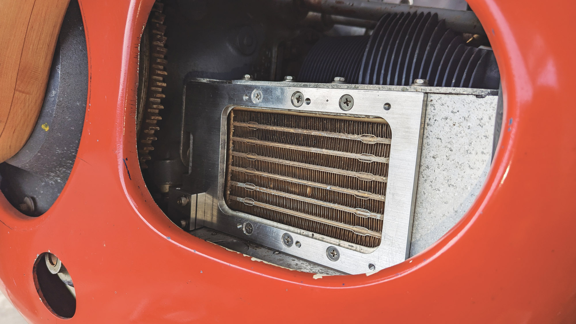
Some engine configurations, however, don’t allow the installation of a Vernatherm; this includes engines originally built without provision for an oil cooler that were later modified using an oil cooler adapter. The O-290-D engine on my Hatz biplane is one of these. Without it, and no winterization kit, the “improvised means” of blocking airflow to the cooler usually means strips of duct tape added or removed as the seasons change…a crude solution at best. I found that my oil cooler needed to be completely covered when the air temperature was below 45° F or so, completely uncovered above 90°, and partly covered to a varying extent in between.
Duct tape is better than nothing, but it’s a hassle, and it’s hit or miss predicting just how much is necessary on any given day, so I started thinking of some sort of adjustable baffle to control the airflow. Of course, I’m not the first person to think of it, and it turns out the folks at Anti-Splat Aero sell a nifty air shutter for just this purpose. I considered making my own, but for the $109 cost of the Anti-Splat shutter it just wasn’t worth the time to design and build a homemade one.


Planning and Fitting
The first step was to figure out if and where it would fit. It’s sized to fit the typically used oil coolers, but there also needs to be room for the control arm and cable. I downloaded a picture from their website, imported it into my CAD system, and scaled it according to the dimensions they provided. Printed out, I had a template that I could lay against the oil cooler to figure out the clearances and decide where the arm and cable would fit. Once I was satisfied, I went ahead and ordered the shutter along with a 10-foot ratcheting control cable to reach the back cockpit.

Anti-Splat provides the shutter without any mounting holes, leaving it up to the customer to drill the holes as appropriate, recommending that they be in line with the existing line of rivets to avoid interfering with the sliding parts. The front mounting holes on the oil cooler (already used to hold the front baffle on my plane) are approximately on that line but closer together than I liked. I decided to make a 1/4-inch-thick spacer plate to provide a solid mount for the shutter and space it out slightly, so I used the original screw locations to hold the spacer to the cooler with the baffle sandwiched in between and additional screws farther apart to hold the shutter to the spacer.
I started by cutting the opening to match the opening in the baffle. Since I don’t have CNC machines, I first drilled larger holes to make the rounded corners before cutting the rest of the opening out with a 1/8-inch end mill, then drilled the necessary holes and cut a clearance for the cable fitting.

Building the Control Mechanism
Next, I made the cable anchor block for the shutter end, with a slit so the mounting bolts would clamp it tightly around the cable housing. There was some question about how to rig it: Pull to open, or pull to close? Asking in some online forums elicited about equal opinions either way. In the end, I chose pull to open, both for better cable routing but also because it seemed more positive;
it seemed better to be able to open it and not close it than the converse.
After verifying the cable operation with a temporary assembly on the bench, I turned to the other end of the cable. As it’s an infrequently used control, and to avoid interference with the mixture and carburetor heat controls, I chose to mount it between two tubes farther forward under the instrument panel. After some playing with cardboard to get the angles right, I made a simple crossbar to attach between the tubes with two Adel (cable) clamps.

After drilling a clearance hole for the cable in the lower part of the existing baffle, I mounted the spacer to the cooler with flathead screws, then attached the shutter itself and the cable anchor.
I experimented with various arrangements of the cable to find the best routing. The cable itself runs alongside the mixture and carb heat cables on the side of the front cockpit, secured at each tube crossing with a cable clamp. At the control end, I attached the mount with one clamp in front of its tube and the other in back. This put it on an angle in order to point the cable outwards and clear the passenger’s elbow.

After passing through the firewall, the cable runs above the intake manifold alongside the oil cooler hoses before dipping down and curving up to the shutter. It’s important to not bend the cable too tight; the manufacturer recommends a minimum 6-inch radius. Under the intake would have been a slightly straighter shot, but I wanted to keep it farther away from the heat of the exhaust. As it was, I ran it through a length of rubber tubing to protect both the cable and anything it might rub against.
Finishing Touches
Once the cable routing was established, I cut the cable to the final length, removing about 30 inches from the 10-foot cable. The housing is easily cut with a Dremel tool and a cutoff wheel, while a heavy diagonal cutter took care of the inner wire.
All that remained was to connect the cable to the control arm on the shutter. The fitting provided by Anti-Splat (but ordered separately) has a single 5mm set screw to hold it to the cable. For redundancy, I added additional shaft collars above and below. The upper one is right against the arm fitting so I can always pull it open even if the set screw in the arm lets go, while the lower one acts as a stop against the cable housing so pulling it open doesn’t stress the arm at the end of its travel.

Final Thoughts
Some people have questioned whether the shutter will still restrict the airflow even in the fully open position. Admittedly the openings are smaller than the opening in the front of the cooler, but the actual opening through the oil cooler itself, between the tubes and fins, is considerably smaller. One member of the Biplane Forum worked out that the actual open area of a typical oil cooler of this type is less than 2 square inches. As the shutter opening is over 9 square inches, I’m not too concerned. The spacer also allows air to spread out and flow behind the blocked portions of the shutter so it can move through the entire cooler, not just the space directly behind the openings.

It is, of course, one more thing to pay attention to during preflight as well as in flight, but it’s worth it to keep the engine happy. Another benefit is that even on days when it will need to be partially or fully opened, it can speed warmup by keeping it fully closed until the engine is warm.
On the first test flight with the shutter on a nice 75° day, I experimented with the shutter position. In cruise at 1000 feet AGL after 15 minutes of flight with the shutter closed, the oil temperature was at 200° F and still climbing. Opening the shutter caused an immediate temperature drop, and it stabilized at 180° with it less than half open. A few weeks later on an 85° day, it still needed to be partly closed to hold 180°. I think it will work out well.


