This month we’ll discuss electric trim and flaps as utilized in Experimental aircraft. Most aircraft kits are designed around either manual or electric control of trim and flaps. If your preference is electric control, this article shows you how to wire the motor control system. It does not cover the actual installation of the control surfaces, motor, or control linkage.
Electric Trim
Electric trim systems have become more popular in recent years. Pilot concerns about unreliable relays, runaway trim, and overly sensitive feel are now mitigated with solid-state trim control systems. When adding electric trim there are three methods you can choose from:
- Traditional wiring with a relay deck and pushbuttons on the stick, or momentary rocker switches on the instrument panel. Ray Allen Company makes a relay deck for this purpose.
- Stand-alone, solid-state trim control system like that sold by TCW Technologies.
- Integrated, solid-state trim control system like that made by Vertical Power. The trim control system is integrated with many other electrical functions in order to simplify wiring.
Adding an electric trim system is often lighter than a conventional cable and crank system, especially in the pitch axis.
Trim control systems can automatically adjust the speed of the pitch trim motor so that it moves more slowly while in cruise and moves at normal speed while in the pattern. This is controlled by either airspeed or flap position, depending on the system.
Most Experimental aircraft use trim servos from the Ray Allen Company, and we’ll focus this article on the assumption you’re using Ray Allen servos. These servos are self-contained units that include the trim motor as well as a position sensor.
The Ray Allen trim servo (models T2-7A-TS, T2-10A-TS, or T3-12A-TS) has five 26 AWG wires, as shown in Figure 1.
Two white wires power the trim motor. Reversing the positive and negative connections to the trim motor controls the direction of motor travel. This is done conventionally using switches or relays, and it is done in the Vertical Power system with solid-state circuitry. Each trim motor should be protected with a 1-amp circuit breaker.
The position sensor connects with three wires—white/green, white/orange, and white/blue. The three wires are wired directly to the position display, which is typically an EFIS, VP-X, or LED indicator bar. As the control arm on the trim motor moves in and out, the voltage on the position feedback line (white/green) varies between 0 volts and the reference voltage (typically +5 or +10 volts). This variable voltage is read by the display and converted into a format that can be displayed for the pilot.
Ray Allen makes a nice 5-conductor wire with matching wire colors, and I recommend using it to wire the trim motors.
Electric trim can be installed on the pitch, roll, and yaw trim axes of the airplane. Each type of aircraft is the same electrically, but the physical installations are different and not addressed herein. If you are installing trim on all three axes, be aware that most EFIS displays only support two axes. Knowing the pitch trim setting prior to takeoff is essential, so that requires an indicator. You can then decide if yaw (rudder) or roll (aileron) is the best to show on the display, leaving the remaining axis without an indicator. My recommendation is to forgo the aileron indicator, as aileron position can usually be felt in the stick or you can view the trim tab on the aileron from the cockpit. And it’s easy to overcome once in flight if set incorrectly. The rudder trim setting cannot be verified easily prior to takeoff without a cockpit display indicator. Another option is to use the two indicators on the EFIS, and add an LED bar indicator in the instrument panel.
Auto-trim modules are now available with many autopilots. While the autopilot is engaged, the auto-trim module takes control of the pitch-trim servo and automatically relieves pressure on the autopilot pitch servo as needed.
Ray Allen servos are designed to run at 14 volts, and the VP-X system provides regulated 14-volt power to the trim motors so they can operate safely in 14-volt or 28-volt systems. If you’re running a 28-volt system without using Vertical Power, you’ll need to install a voltage converter module (Figure 2) and power all of the trim circuits from it.
There are several ways you can wire the trim motor, and we’ll show three of them here. The first way requires a double-pole, double-throw (DPDT) momentary toggle switch that is off when in the middle default position. Moving the switch to either off-center position reverses the polarity of the motor and drives it in one direction or the other. The position sensor wires are connected to the EFIS display to show the trim position. This configuration is used with a switch on the instrument panel and not with pushbuttons on the control stick. Figure 3 shows the wiring and back side of the switch.
The configuration shown in Figure 4 is typically used with control sticks that have pushbuttons on them. The trim control module can be a relay deck or a solid-state trim control module (preferred).
The Vertical Power Electronic Circuit Breaker System is shown in Figure 5. It controls the motor with solid-state circuitry and sends the trim position information directly to the EFIS via a data line.
Electric Flaps
Electric flap systems have become popular in recent years, and kit plane manufacturers are designing them in as standard equipment. At a high level, the flap system is similar to the trim system. You have a motor that reverses direction by flipping the motor polarity, and an optional position sensor that reads the flap position and shows it on the EFIS.
The simplest way to control the flap motor is to install a momentary DPDT flap switch that changes the motor polarity. It is very simple and inexpensive, but you have to hold the switch in order for the flaps to move. Also commonly installed is a switch that stays in the Up position. Van’s Aircraft customers especially should not use such a system, as the flap motor can run continuously if the flap switch is left in the wrong position. The pilot has no way of knowing that the flap motor is running and wonders why the expensive flap motor needs to be replaced often.
The next level of functionality comes from using a stand-alone flap controller. While the features vary, a flap controller typically allows you to raise the flaps with one motion, limit the flap motor run time, and manage conflicts if more than one flap switch is installed. TCW Technologies manufactures such a flap controller.
More advanced functionality comes from the Vertical Power system, and includes the above-mentioned features plus intermediate flap stops, slow retract at go-around, and others as part of an integrated system.
The position sensor is optional, and most EFIS displays show the flap position. The most common flap position sensor is the Ray Allen POS-12.
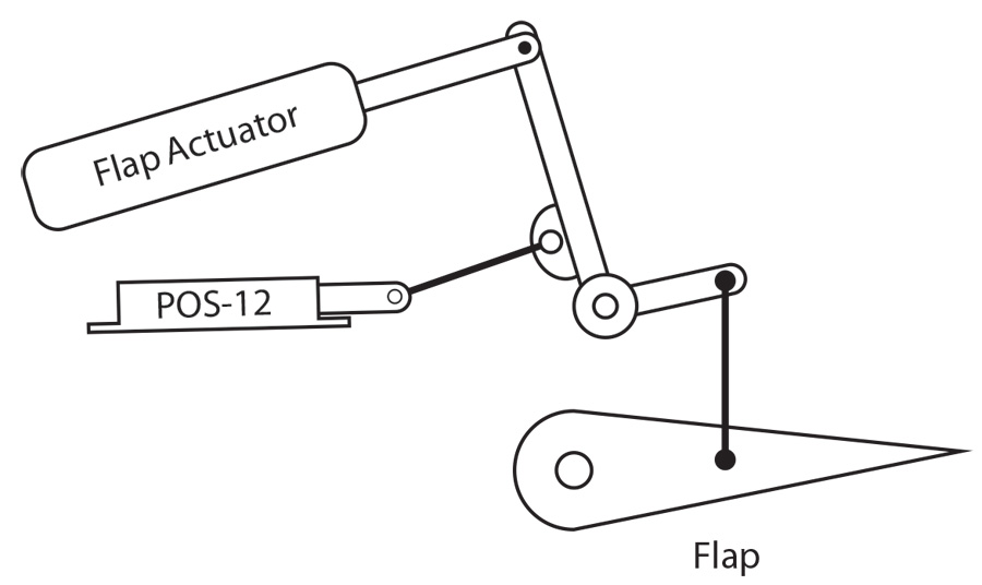
Install the position sensor on the flap motor bellcrank or nearby. Figure 6 shows a conceptual drawing of how the electric flap actuator travel is much longer than the 1.2 inches of travel for the POS-12. Mechanically, this all works out because the POS-12 is located lower on the bellcrank where there is less linear travel.
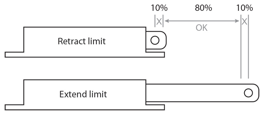
The POS-12 should have some extra slop at the extreme ends of the flap actuator travel (Figure 7). As a rule of thumb, allow an extra 10% (about 0.1 inch) of extra slop at each end of travel so that the position sensor does not bind. If it binds it cannot measure travel, and therefore the readings will be inaccurate. Additionally, the POS-12 is not accurate at the extreme 10% ends of its travel.
There are several ways you can wire the flap motor, and we’ll show three of them here. The first way requires a double-pole, double-throw (DPDT) momentary toggle switch that is off when in the middle default position. Moving the switch to either off-center position reverses the polarity of the motor and drives it in one direction or the other. The optional position sensor wires are connected to the EFIS display to show the trim position. Figure 8 shows the wiring and back side of the switch.
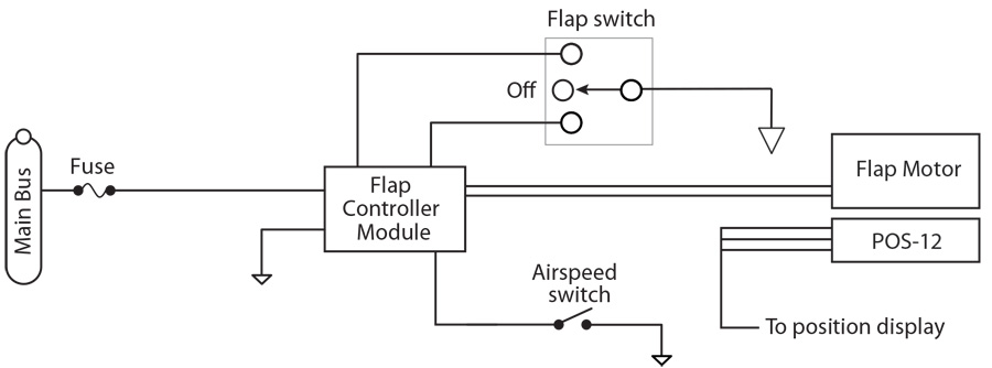
The next flap configuration (Figure 9) uses a flap control module. The advantage of such a system is that the flap switch does not have to carry the full current of the flap motor, and therefore you can use one of the switches on the control stick for flap functions. Another advantage is that the controller can raise and lower the flaps with a simple momentary press of the flap switch.
The Vertical Power Electronic Circuit Breaker System is shown in Figure 10. In addition to the advantages mentioned above, it controls the motor with solid-state circuitry and sends the optional flap position information directly to the EFIS via a data line.
Read the Book
Hopefully this article has helped you understand electric trim and flaps in Experimental aircraft. It is an excerpt from my new book entitled Aircraft Wiring Guide. For more information, or to order a copy, visit www.aircraftwiringguide.com.

![]()
Mark Ausman currently flies an RV-7 that he finished building in 2006. He was founder and president of Vertical Power and has served as an EAA Director since 2011. He flew with the U.S. Navy as a Naval Flight Officer on board the P3-C Orion. He lives in California with his wife and three children.


