 There comes a point in the construction of any aircraft when it is easier to stop and think about the interior rather than waiting until the aircraft is finished. There are companies that make beautiful aftermarket interiors for some of the more popular homebuilt aircraft, but I’m not aware of any for the Hummingbird. Luckily, I’ve built enough aircraft to know when to stop the construction process even though it pains me to do so. Starting the interior on my own would be akin to me baking brownies in the kitchen. I did that once, and only once, as it was made very clear that I was treading on thin ice (or frosting!). Carol has done all the interiors for our aircraft, so for the most part I just lend a helping hand.
Figuring out the interior is almost as bad as trying to figure out the paint scheme as there are so many choices. Plus the chosen colors for the exterior paint scheme help determine the colors of the interior. No sense installing a red interior with a green airplane unless we are trying to make it look like a watermelon! We finally landed on a paint scheme that had red, black and silver in it. It was kind of funny that only after we designed the paint scheme, we realized it looked a lot like our RV-10. We must like those colors.

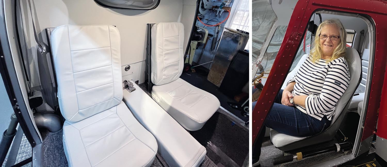
Helicopters for the most part have a large glass bubble, which contributes to the awesome view. The drawback is that the big bubble lets a lot of sunshine into the cockpit. Couple that with most flights being at 1000 feet or below so you never really get high enough into cooler air, and it’s clear that light colors should be chosen for the interior. Carol decided on a light gray for the seats, with a little darker color for the carpet, not much of which shows anyway. The only dark area is the covering for the instrument panel. It needs to be black so it does not reflect in the windshield. Unfortunately, that makes the instrument panel quite hot, so I put many snap bushings into the top of it for ventilation. I also observed that I needed to get the instrument panel covered prior to installing the windshield.
Pattern Work
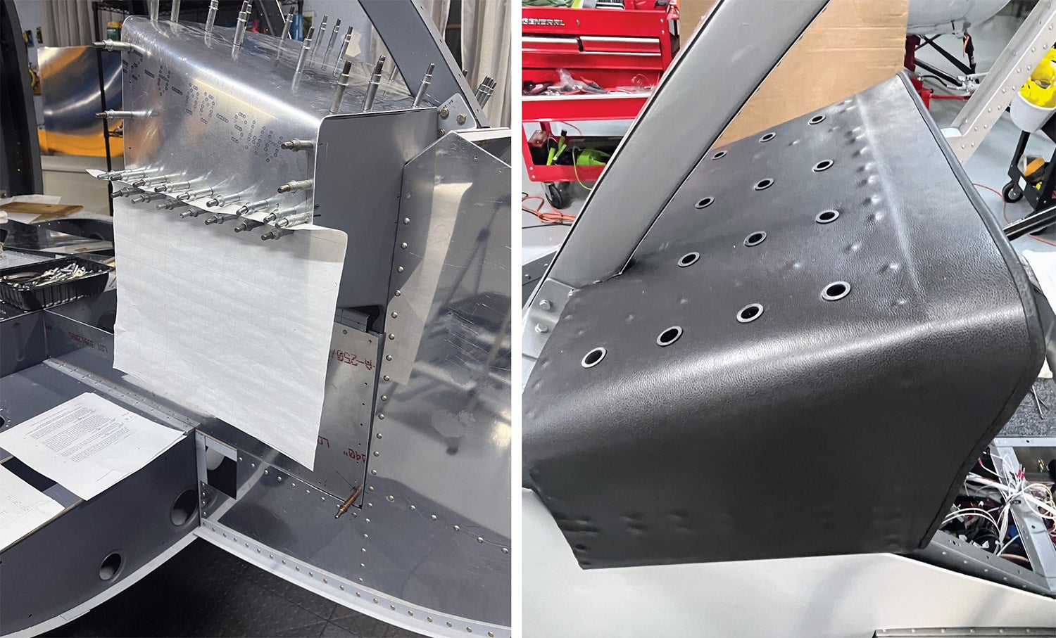
Cutting all the patterns was a two-person job. We traced onto paper the outline of the ceiling and side panels prior to installing them, and that made it easier to create a pattern. A few of the ceiling panels were already riveted in place, so it was a matter of trying to trace on the paper while holding it over your head. That was challenging at times.
It’s amazing how much material it takes to do an interior. Carol notices things I don’t, like making sure the grain is going the same way for all the pieces. Heck, I never had to pay attention to that when I was cutting aluminum. I just laid out the parts on the sheet in the best way to minimize waste. Not so with the carpet and interior wall coverings. I forget how many yards of material she ordered, but it seemed like way too much at the time. As it turned out, we didn’t even have enough and had to reorder more. Carol will remind me she had to redo several covers due to lack of proficiency.
I was allowed to do the instrument panel covering by myself, and that opened my eyes as to why so much material was wasted. My goal was to make it in one piece, and it had compound curves and wrapped from one side of the cockpit to the other. Tracing it in the aircraft allowed me to make a pattern prior to cutting and wasting any material. We had a 1-yard piece of black Ultraleather, and it was just enough so I didn’t want to mess it up. It fit quite well when I was finished and gave me confidence that making paper patterns was the way to go.
Once I got all the patterns traced, Carol did her magic and cut out the Ultaleather pieces and glued them to the aluminum. In the case of the doors, she also added some pockets and even embroidered the Open/Close instructions with arrows on the door panels. It looks much nicer than decals!
The carpet was a wrestling match and had even more waste than the side panels. There are huge areas cut out over the top of the footwells. The carpet is very hard to cut with normal scissors. We finally bought some real carpet scissors that worked great and then discovered that electric metal shears also work well. Carol managed to put a nice edging on all the carpet edges.
Soundproofing
One of the steps that is important with regards to the interior is to make good use of soundproofing. We’ve done that in all our aircraft and, coupled with noise-canceling headsets, the cabin noise is muffled quite well. We did the same for the helicopter, placing super soundproofing material between the interior and exterior walls. Unfortunately, I had already riveted the larger part of the ceiling surrounding the transmission without thinking, and that was a mistake. The noise level in the Hummingbird is perceptively louder than our RV-10. The interesting thing is that a sound meter shows close to the same level in both aircraft, so we are thinking it is a different frequency that is causing the problem, specifically the transmission. We are still working on solving that problem, but are getting close.
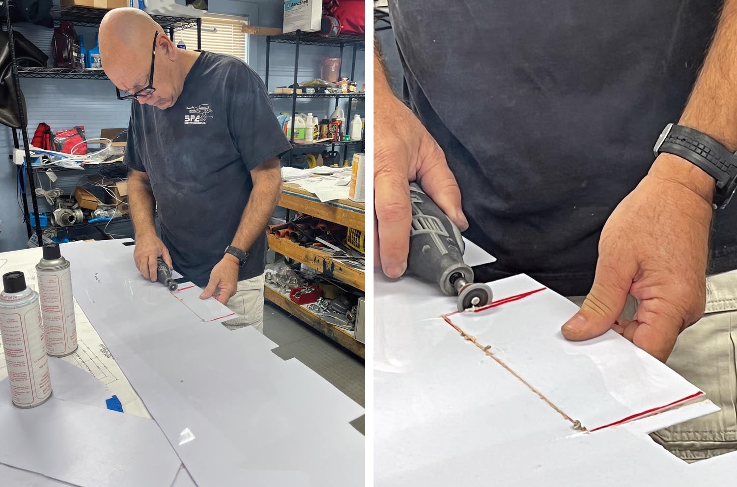
I found that a Dremel with a diamond cutter wheel worked well for cutting plastic prior to covering it with the fabric. Using it at a slow speed did not melt the plastic, and very little cleanup of the edges was required. We used 3M Hi-Strength Spray Adhesive to attach the covering to the plastic and aluminum. We’ve used that before and it seems to hold up very well in the cockpit environment.
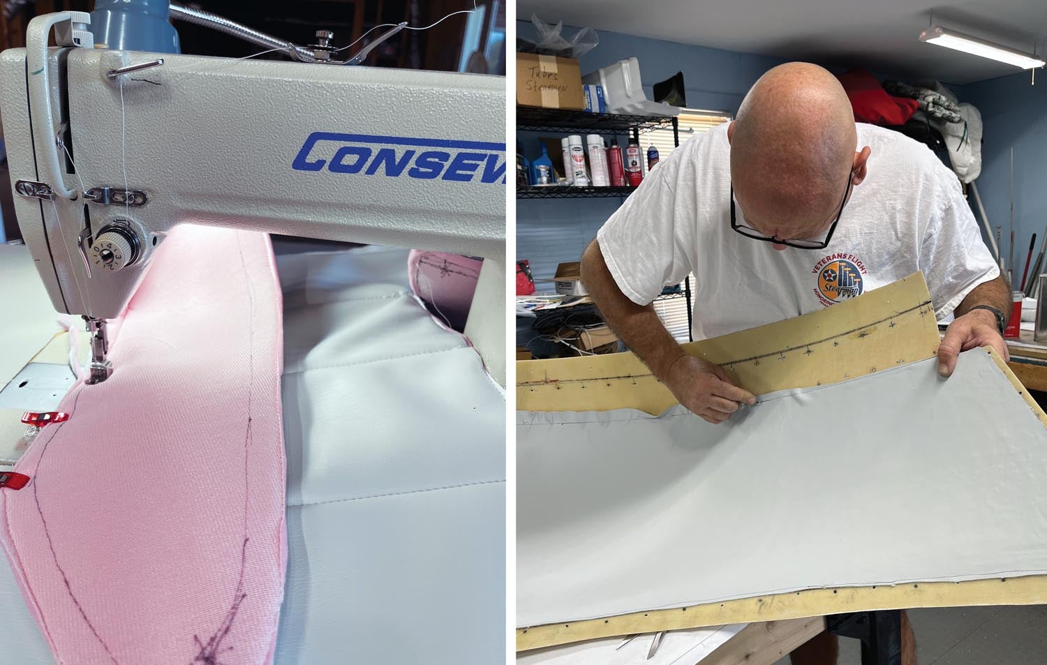
Carol disappeared into the basement for a couple of months to cover the seats. I think it was about 10 years since she made the seats for the RV-10, so the learning curve was in full play again. There was certainly a lot of grumbling, but the results are fantastic! They look so good she even commented about redoing the seats in the RV-10, as after 14 years and 2200 hours, they are starting to look worn.
Once the interior pieces were fabricated, I permanently reinstalled all the aluminum ceiling and side panels, using CherryMAX rivets. The pneumatic puller was needed for these, as there were close to 400. After that, it was time to install the rotor head and blades.
It’s Alive!
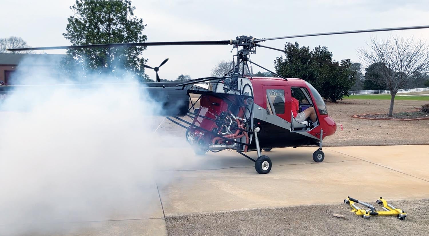
Now it was time to make some noise with an engine start. I always look forward to that, as it is neat to see all the engine instruments come alive. There was a lot of smoke coming out of the exhaust on the Hummingbird during the first start, and I knew exactly what the cause was. The Thunderbolt engine came with a lot of preservative oil in the cylinders. Normally, after the engine is installed and ready to run, I will remove the lower spark plugs and the oil will drain out of the cylinders. With the spark plugs removed, I will rotate the engine by hand and it forces any remaining oil in the cylinders out. Probably because I had installed the engine the day after gallbladder surgery, I wasn’t thinking far enough ahead on the difference in the helicopter installation. In this case, the engine was inclined at a 60° angle. When I pulled the spark plugs and rotated the engine, some of that oil drained into the exhaust system and down into the muffler, where it was heated and smoked during start-up. No big deal. I probably should have thought about it and removed the mufflers to clean them, but I didn’t think about it.
All indications were normal, but I did shut the engine down and checked for leaks. There weren’t any, so it was time to do the next big thing—rotor engagement. I made sure the parking brake was set, as the torque from rotor engagement can spin a helicopter on wheels. On skids, it is not a big deal.
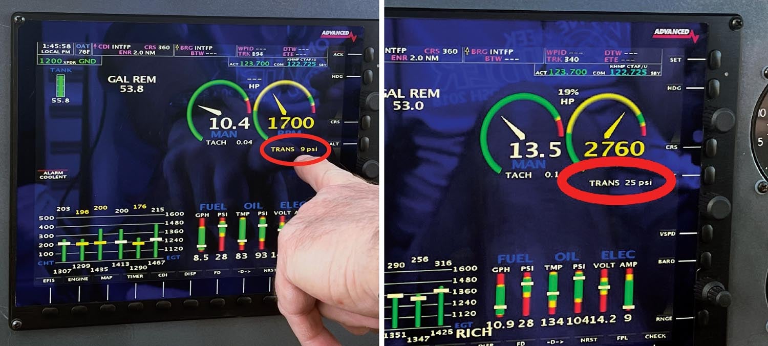
Rotor engagement was fine, with the engine tachometer and rotor rpm indication matching as they should at the 2000 rpm mark. However, I had a transmission oil pressure indication at 9 psi. The minimum is 10 psi. I shut down and decided to adjust the oil pressure relief valve on the transmission. It’s basically the same setup as on the engine itself, so I adjusted it two turns clockwise. The second rotor engagement showed the same result, so I repeated the adjustment on the relief valve. After two more engagements, and with the oil pressure relief valve at the full clockwise position, I still had 9 psi or less. It was time to quit, as I didn’t want to damage anything.
I brought the helicopter back into the hangar to start troubleshooting. I took the path I normally do, and that is assuming I must have done something wrong or perhaps I had a bad sensor. I checked all the wiring to the sensor and measured the proper voltages. I swapped the engine oil-pressure sender with the transmission pressure sensor and added an extra fitting so I could install a direct-reading oil-pressure gauge. On the next engagement the results were the same—a below-minimum pressure indication on the EFIS and the direct-reading gauge.
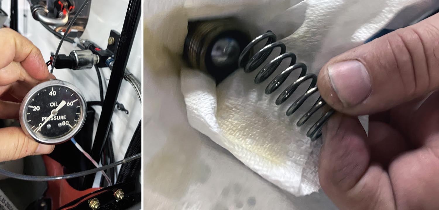

I called Vertical Aviation and spoke with Brad Clark. He assured me that nothing had been damaged, as there is plenty of splash lubrication. We decided I should disassemble the oil pressure relief valve assembly and make certain there wasn’t some contamination on the ball bearing, which would prevent it from seating. So, I did that, and when the ball and spring finally came out of the transmission sump, the problem was quite visible. Somehow during assembly, the ball bearing had been placed at the wrong end of the spring. I placed it on the proper side and was rewarded with good transmission oil pressure on the next engagement. The range is supposed to be from 10 to 30 psi, and after one adjustment it was steady at 25. Wonderful!
With the weight and balance completed, including the necessary paperwork for the FAA, it was now time for the airworthiness inspection. The Hummingbird was going to move from a project to a real aircraft. The fun factor would soon be increasing!


