The usual setup for my lathe is to have the compound slide set to 45 degrees and the tool post square to the spindle axis. While this setup is good for about 50 percent of the work I do—OD turning, facing, parting, grooving, boring, and 45-degree chamfering—it also means that for the other 50 percent, I’m constantly tweaking the compound slide angle and tool post position.
Chamfers
One of the most common “tweaks” is to change the angle on the compound slide for chamfers with “unequal” setbacks. In other words, chamfers other than 45 degrees!
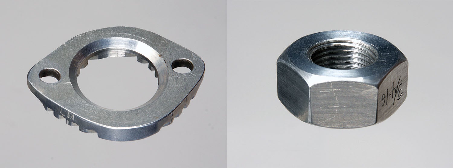
Chamfers with unequal setbacks are often just for looks, but they might be there for structural considerations. Whatever the case, a well-executed chamfer adds a professional touch to any project.
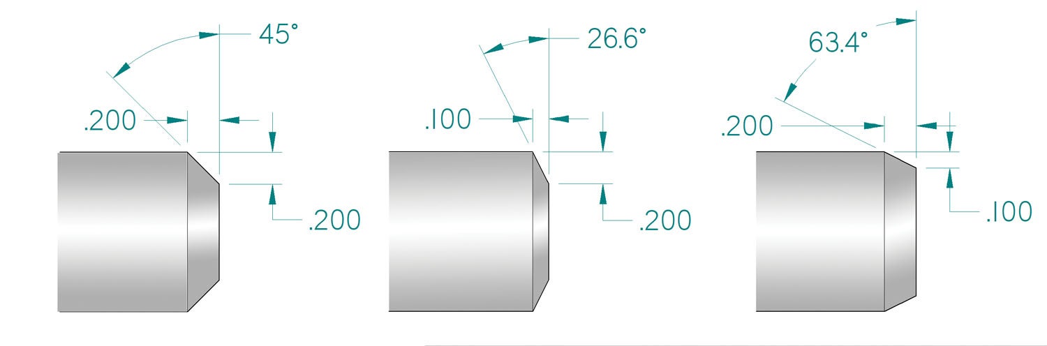
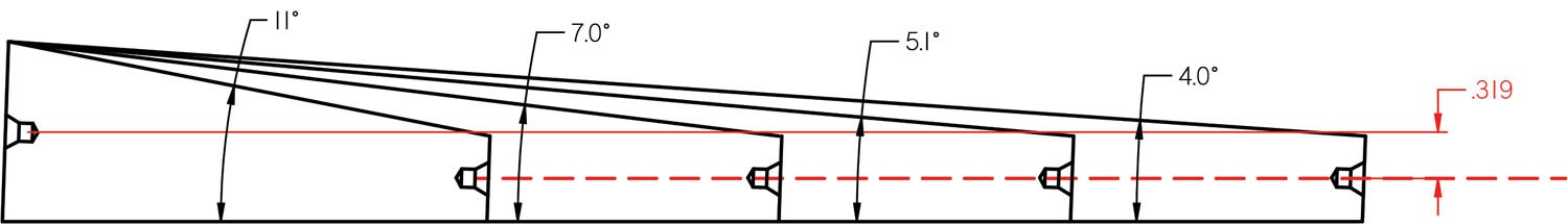
When drawing a chamfer with uneven setbacks, it’s normal practice to call out just the linear dimensions. If the drawing includes the chamfer angle, great! Otherwise, it’s up to the machinist to figure it out. Although the math is easy enough, you can take the guesswork out of it by using one of the many web-based angle calculators. Of course, when I’m drawing chamfers, I always include the angle.
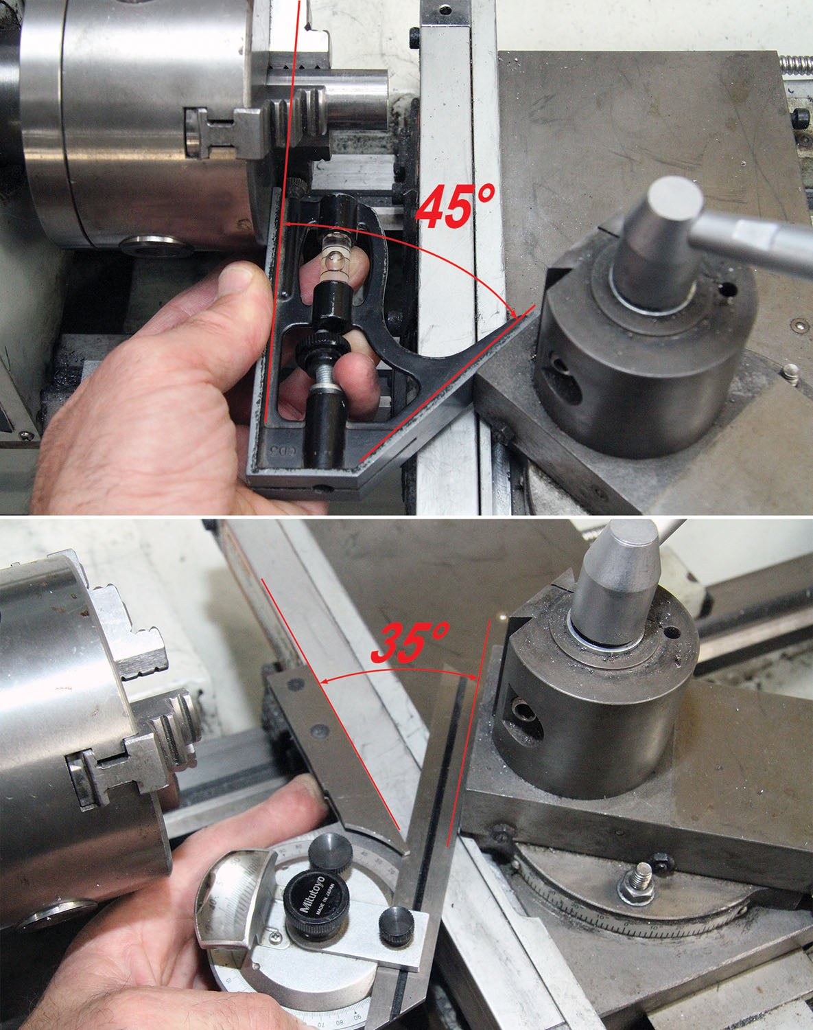
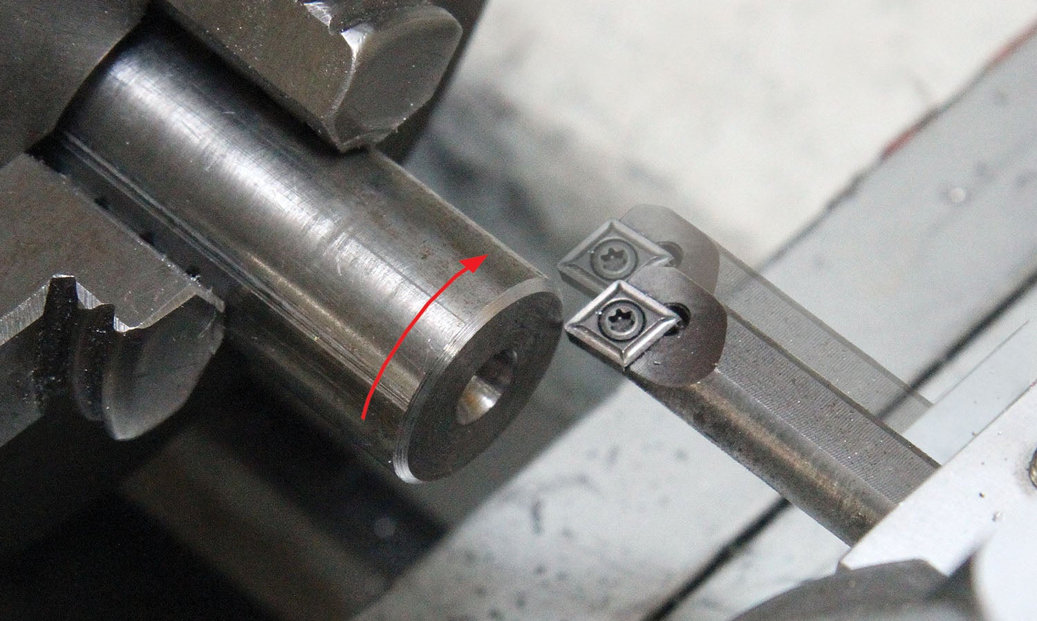
Shallow and small chamfers often can be quickly machined by positioning the long edge of the tool to the edge of the workpiece and making a plunge cut. But more often than not, I set the compound slide at the correct angle and advance the tool to make the chamfer.
Tapers
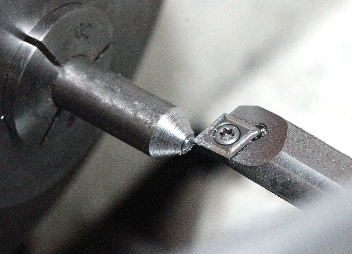
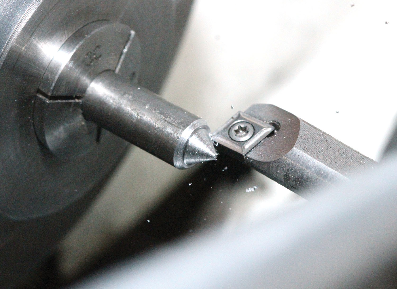
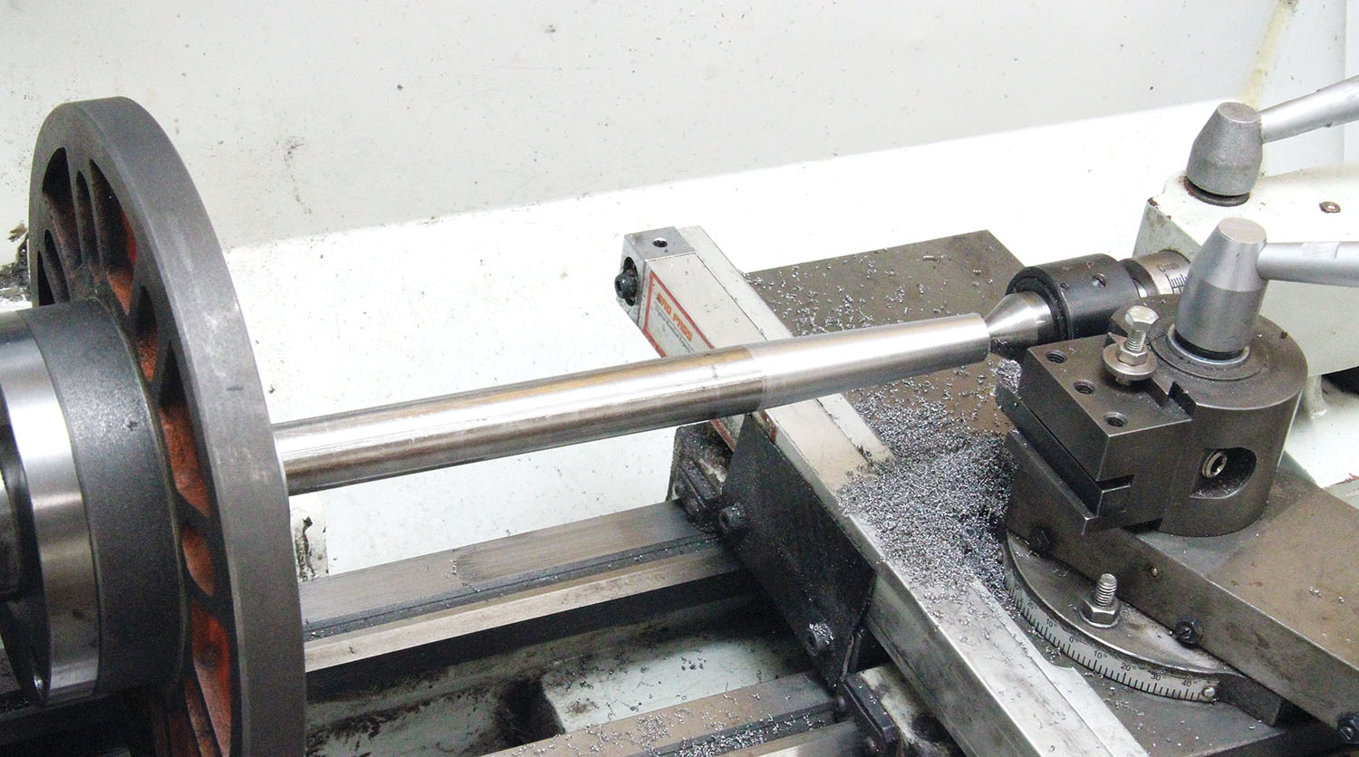
Generally speaking, a taper is a type of chamfer that is either to a point, or longer and more gradual than a beveled edge. Short tapers can be made using the compound slide the same way as a chamfer: Set the compound slide to the desired angle, align the cutter, and off you go! Tapers that exceed the travel capabilities of the compound slide are made by either offsetting the tailstock, or by means of a special taper-attachment accessory. Since no taper attachment exists for my small lathe (they’re typically not an option for small bench lathes), I’ll focus on the offset tailstock method.
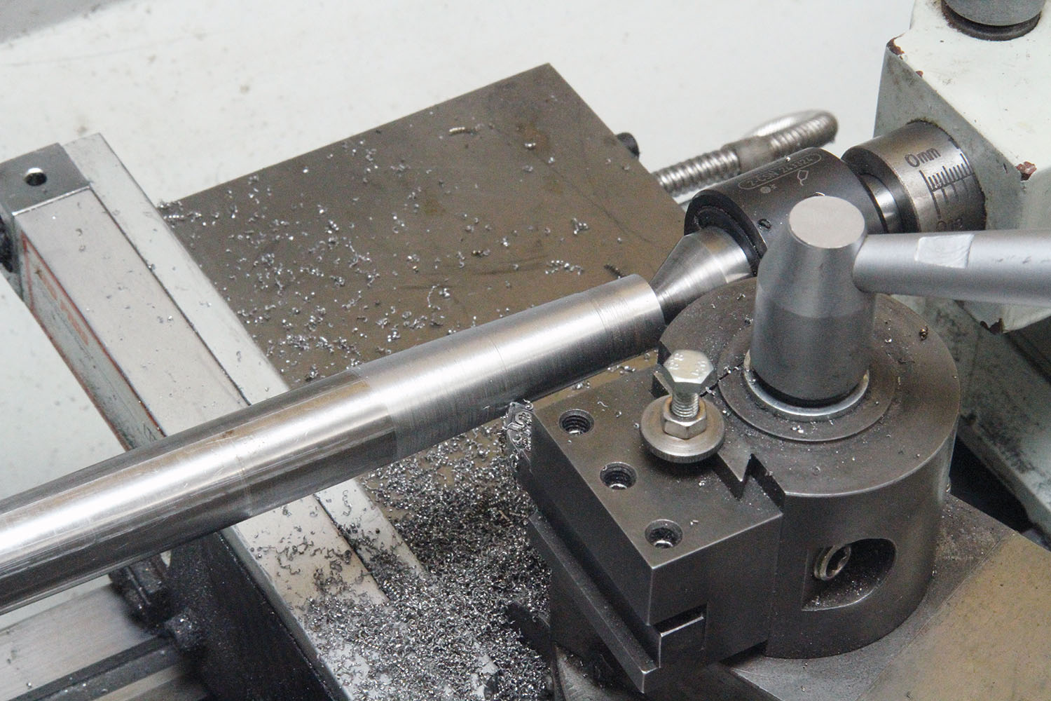
The offset tailstock method takes advantage of the taper “error” that occurs (when machining between centers) when the tailstock center is not perfectly aligned with the headstock center. To make a taper, the idea is to offset the tailstock a prescribed amount in order to generate the desired taper.
How much to offset the tailstock depends on the angle or slope of the desired taper and the distance between the centers.
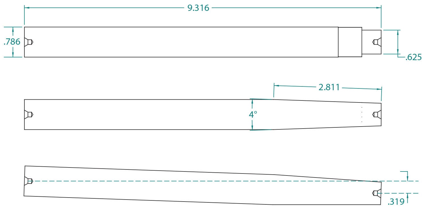
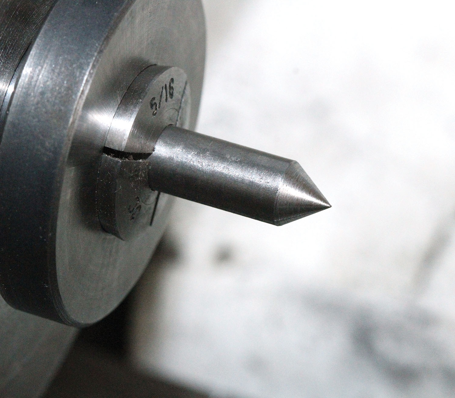
To demonstrate taper turning, I made an alignment drift. This is a tool that comes in handy when you need to coax a spar and strut end to line up with a mounting hole. The material for the drift was a 9.3-inch length of steel bar salvaged from a go-kart axle. The diameter was 0.787-inches (20mm), and it had a small 5/8-inch diameter stub already turned on one end. After some sketching, a four-degree taper looked perfect. CAD software made it easy to get the distance to offset the tailstock. It’s hard to overstate the convenience of sketching with a CAD program. Provided your sketch is accurate, you can derive precise dimensions with a click of the mouse. (Download a free version of Solid Edge 2D drafting software. EAA members can download a free version of SolidWorks.)
With the offset dimension in hand (0.319 inches), it was time to set up the lathe and get started shaping metal.


Tapers and chamfers are just two examples of the endless versatility of the lathe. Of course, we’ve only scratched the surface. Tapers, for example, are usually defined not by the angle, but by the amount of taper per inch or per foot. The resource material available online is almost endless, but if you prefer old-school reference material, it’s hard to beat Machinery’s Handbook. That’s a wrap for this month. Until next time, get back out in the shop and make some chips!


