“Gulf Coast Regional Airport, Experimen—N90—Q, currently—ile—orth, inbound for—”
 Drat! The headset is intermittent again!
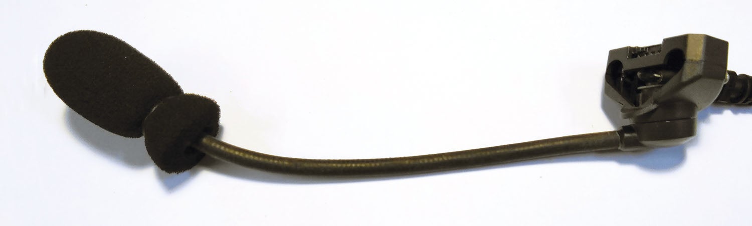
The insulation on the cable from the ear cup to the battery holder had become frayed with age and use, exposing the tiny wires to strain every time the headset moved, causing them to break. Each time they broke, they were carefully soldered together, sometimes with a short patch wire, but this only concentrated the strain at the end of the new repair, and after three failures in the last 10 flights, it was time to look for a better solution. Unfortunately, Bose no longer repairs Aviation X headsets. There had to be a better way than spending 1 AMU (Aviation Monetary Unit) on a new headset when the old one was otherwise perfectly serviceable!
Good practice in aircraft wiring means restricting connections to only the two ends of each wire and avoiding splices or other unnecessary connections in the middle. I was violating that good practice every time I soldered the wires and paying for it with an unreliable headset.
Pins and Barrels
The Bose headset uses a fixed connector in the ear cup, with pins sticking out to interface with the microphone assembly. This carries all the audio and noise-cancelling connections into the ear cups. Inside the microphone assembly are two connectors: one that is held in a molded bracket so it interfaces with the ear cup pins and another that connects to the microphone itself. Neither connector looks like the typical Molex or D-sub connectors used in the rest of the airframe, but careful measurement, online digging, and trial and error revealed that both connectors are in fact commonly used in personal computers and readily available through electronics suppliers. As the frayed portion of the cable only extended for a few inches below the ear cup, the bad portion of cable could be cut out and new connectors installed.
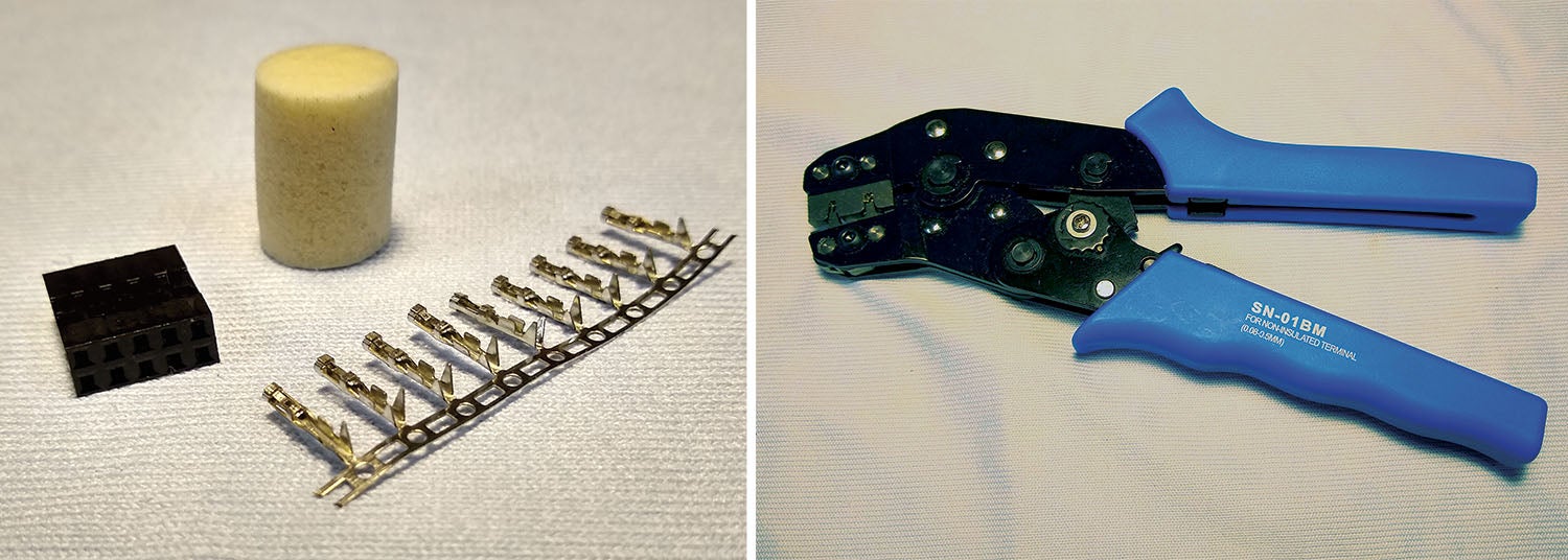
The main ear cup connector is known as a Dupont 2.54 mm “two by five,” meaning there are two rows of five conductors with 2.54 mm spacing between them. This is quite a small connector.
Connector descriptions typically show a measurement that is the distance between individual conductors within the connector. The actual conductors are a matching pair of pin and barrel, which are typically described by the size of wire they carry. There are different manufacturers of connectors, pins and barrels, and it is important to ensure that the style and size of pin and barrel match with the connectors they are intended to be used with.
Crimping tools are normally sold with a reference to either AWG or mm², which relates to the size of wire that will be crimped, as well as a reference to the model of connector system they are compatible with. It can get a bit confusing, but the important part when buying connectors and crimpers is to distinguish between the pitch (spacing) between the conductors in the connectors, and the size of the pins/barrels and the wire sizes they accommodate. For example, the SN-01BM crimper I used for the 2.54 mm connector is good for AWG 28–20, which translates to 0.08–0.5 mm2. Better crimping tools will have a ratcheting mechanism that will not release the pin/barrel until it has been fully crimped.

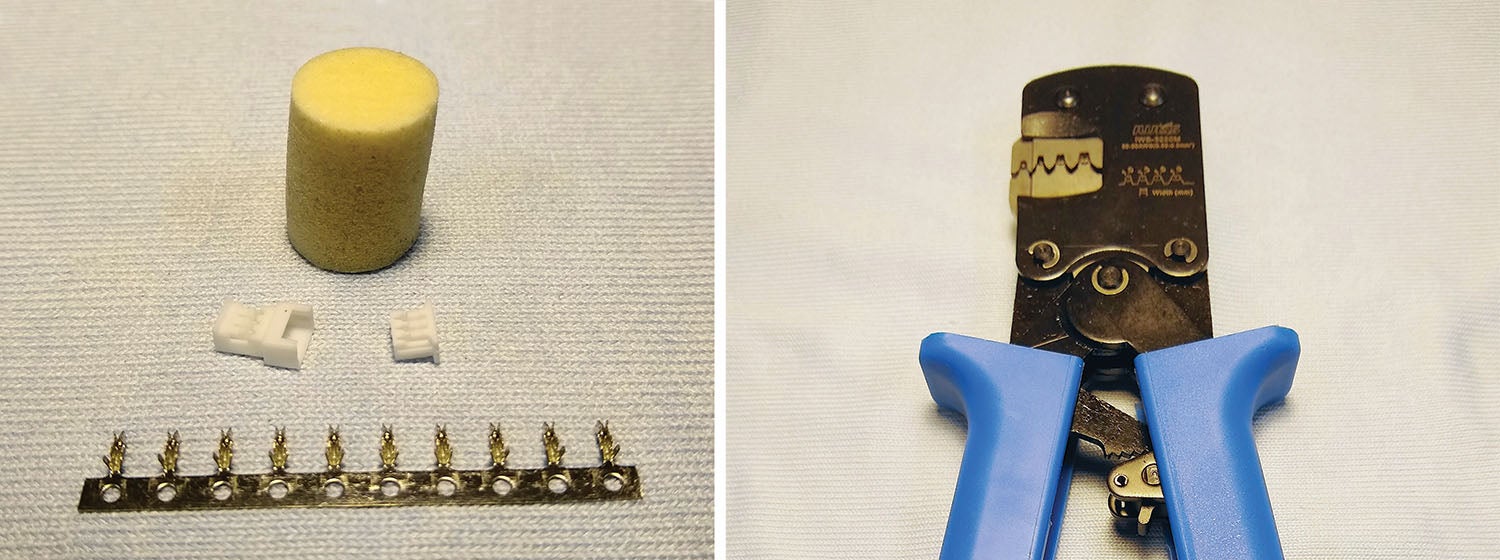
The microphone connector is even smaller. It is a 1.25 mm 3-pin Molex 51021/51047 PicoBlade. Similar to the above, the 1.25 mm refers to the pitch of the conductors. The 51021 end houses the female barrels that connect to the end of the cable. The 51047 houses the pins and is on the microphone end of the connector. These are really small! When the ears of the pins/barrels are parallel to each other, they are only 0.04 inch (1 mm) apart. Working with them feels a bit like being an apprentice watchmaker. Unless you are blessed with the vision of a teenager, reading glasses and magnifiers are mandatory equipment.
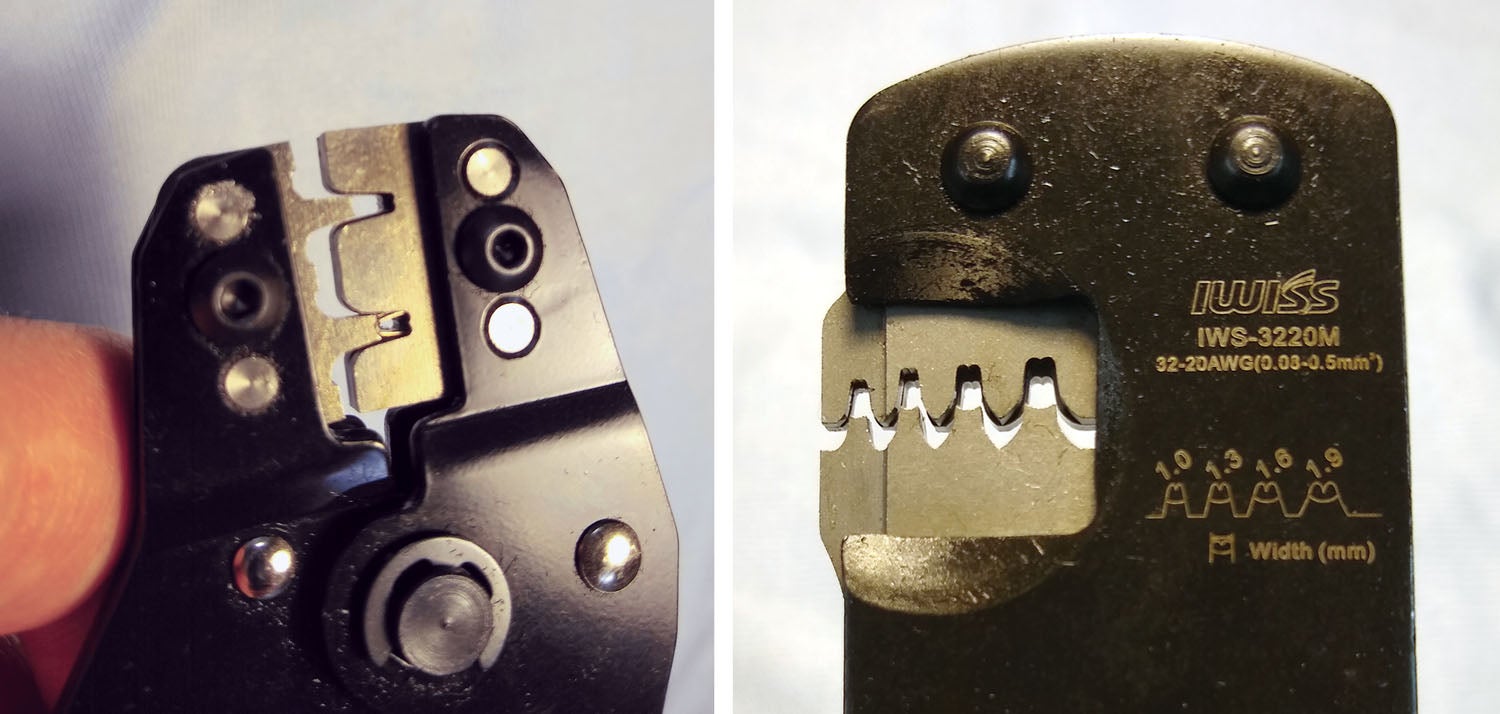
For the PicoBlade connectors, I used an IWS-3220M crimper, which is good for AWG32-20 or 0.03-0.52 mm2. The jaws move a little differently from larger crimpers, but the principle is the same.
Stripping the wires requires a tool that can adjust down to very fine wires. I found a Stanley 84-213 stripper for 10–26 gauge wire works well, but it must first be adjusted to the correct size for the headset wires. Practice stripping the ends of the wires first, before cutting them to final length.
Assuming that the microphone (pin) end of the connector is in good condition, repairing the headset will require working only with the barrels—not the pins.
Each barrel has two sets of ears for crimping around the wire: one that closes around the insulated part of the wire and another that closes around the exposed wire end. Use some of the practice wires to set the stripping tool, and place a test wire end into a barrel to see how much exposed wire is necessary. With these small pins, only a small amount of exposed wire is needed—anything more would extend into and interfere with the area where the pins slide into the barrels.
There is one wire that runs between the connectors. Using a jeweler’s screwdriver, it may be possible to lift the locking pins of the connector, extract the barrels from the old connectors and reuse the same wire and barrels in the new connectors. If not, be sure to save a length of wire from what will be cut off the end of the cable so a new wire with two new barrels can be constructed.
One Step at a Time
The actual process of repairing the headset is as follows:
- Remove the two screws holding the microphone assembly to the ear cup using a Phillips (star) #0 screwdriver, and pull the microphone assembly off the ear cup.
- Remove the two screws holding the two halves of the microphone assembly together.
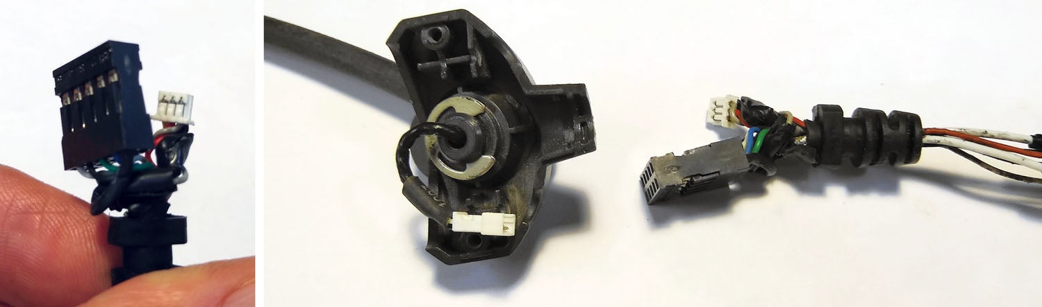
- Disconnect the white 3-pin PicoBlade connector from the microphone.
- Take some pictures and/or write down the colors of each wire and which position they go into on each connector. Depending on the manufacturer, the new connectors may or may not have their positions numbered, so be careful to take steps to ensure that the new connectors will be assembled with the correct wire colors in the appropriate positions.
- Cut the old cable at a point where the degraded part can be discarded.
- The old grommet where the cable enters the microphone assembly will be reused. Remove the grommet from the cut part of the cable, which will be discarded, and work the remaining good part of the cable back up through the grommet. This requires some patience. It may be easier to trim back the outer insulation of the wire first (see next step). Some dielectric grease may also be helpful to squeeze the grommet over the cable. The idea here is to get the grommet all the way over the black insulated cable; otherwise a new strain point will be created right where the cable goes into the grommet.
- Carefully strip approximately 2 inches of the outer black insulation from the cable, exposing the wires inside.
- Cut the wires about ½ inch from where they come out of the grommet and strip the ends.
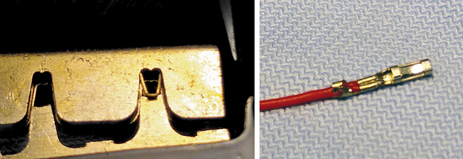
- Place the open end of a fresh barrel into the slot of the crimp die, with the insulation-crimping ears flush with the jaws on the side of the tool with lettering on it. Partially close the crimper to hold the die in position without actually crimping it yet.
- Place the stripped wire end into the end of the barrel so that the insulated part of the wire will be covered by the first set of ears on the barrel.
- Squeeze the crimper. Tug on the barrel to ensure it is securely crimped to the wire.
- Repeat step 11 for the other wires. Make sure the correct size barrel is used for each color of wire. Five “large” barrels and three “small” ones will be needed (they’re all very small!).
When placing the new barrels into the new connectors, it may be helpful to get them all started together, then press each one individually until it locks into place with a clicking sound. Tug on each wire to ensure it is locked in position. If it doesn’t lock into place, the barrel may be upside down. Rotate it 180 degrees and try again. The hard part is now done! Plug in the new microphone connector, place the “two by five” in one side of the microphone shell and reassemble. Test in the airplane to ensure everything works and go fly!
If the old headset cable is not salvageable, a new multi-conductor cable could be acquired from an electronics supplier. However, be careful to ensure that the outside diameter of the wire is no greater than the old if you want to reuse the old grommets. One possible cable could be Digi-Key part no. T1351-1-ND (around $3). However, this is not a shielded cable and may or may not allow some electrical noise to intrude. Before proceeding with this, make sure the battery box end can be opened and confirm what kind of connectors are required. I could not get the screws to release on mine and gave up, as I was planning to leave this end of the cable alone, anyway.

The total cost of the repair was just over $60. This included acquiring a good stock of connectors, barrels, a new wire stripper and two new crimpers, all of which can be used on other projects (“It’s an investment, dear!”). The end result is a slightly shorter cable, but hopefully the repair will significantly extend the life of the headset.


s")


