A loyal reader writes, “I have a homebuilt Bugsmasher with a couple of com radios. They are a FlashBoom 32X and a LoudenWhapper 22A. I have each one connected to a separate switch and through the switch to my headphone jack. When I switch either of them separately, the audio is fine, but when I switch them both at the same time, the phone’s audio drops and gets all distorted. How do I fix this without installing an audio panel?”
I suppose I’ve heard this same question a few (dozen) times in my career, and I thought I might just put it to bed directly (and send a copy of this article to the readers who ask this question again). While the answer is simple, I thought you might like to see the thought process that gives a simple yet elegant answer.
For those of you of the electronic bent, here is the answer: Trying to connect two radios to a common headset this way is nearly impossible without some intervening electronics. When FB-32X is connected to the headset, all the output section of the 32X sees is the headset. When LW-22A is connected to the headset, similarly, all the 22A output section sees is the headset. But when FB-32X and LW-22A are switch-selected to the same phone jack, the output section of the FB-32X sees not only the load impedance of the headset, but it is also directly connected to the output section of the LW-22A. Similarly, the LW-22A also sees the headset as well as the output section of the FB-32X.
The headset impedance (ohms) is about 150 ohms. If you have two headsets connected at the same time, the impedance drops to about 75 ohms. No problem! We design our radios to easily handle this. To do this, we design the radio output impedance to be as low as reasonably possible to deliver a constant signal to as many as four or five headsets if necessary. This is possible because the output impedance of the radio is relatively low—a few ohms at most. Now you have radio 1 trying to drive radio 2 with a similar impedance and the volume drops in half. Not only that, but the output impedance can be resistive, capacitive or inductive, and there is no way (other than peeking at the internal schematic of the radio) to figure out which is which. The volume will drop, and if FB-32X output is capacitive and LW-22A output is inductive, all bets are off as to what kind of distortion you are going to get.
For those of you not so much of the electronics persuasion, how about an engine analogy? Forget the mechanical problems of design. You have mounted two engines from different manufacturers on the front of your Bugsmasher, with two huge mechanical switches that you can connect to a single prop. Connecting either engine to the prop makes the airplane fly quite nicely, but trying to connect them both to the prop at the same time makes engine 1 try to drive not only the prop, but also engine 2. And vice versa. I daresay you are in for a particularly difficult problem without a complicated series of gears and levers…an engine panel, if you will. Sort of like how an audio panel solves the headset problem.
Fortunately for me, I push electrons, not propellers, and they are a lot lighter and considerably easier to work with. Allow me to introduce a really neat little device that I’ve used a dozen times over the years, the LM386. Originally introduced by National Semiconductor in the mid-1970s, it has gone through a dozen revisions and is licensed by half a dozen manufacturers. It sells from most major electronic distributors for about a buck and a half.
Here are the neat parts about the 386: It is nearly bulletproof. I suppose if you really ham-hand it you can destroy it, but I’ve done some really stupid things with it and it simply smiled and said, “Please don’t do that again.” It comes fixed with a voltage gain of 20, so making a simple unity gain (voltage gain of 0) amplifier can be done for two penny resistors per channel. It also has a maximum supply voltage of 15 volts* so connecting it directly to the aircraft supply (through a fuse/breaker, of course) isn’t a problem. The output is short-circuit limited, so the “oopsie” with a screwdriver (or wiring it into the aircraft) isn’t a big deal. In short (no pun intended), if you destroy this device, please write me and tell me how you did it.
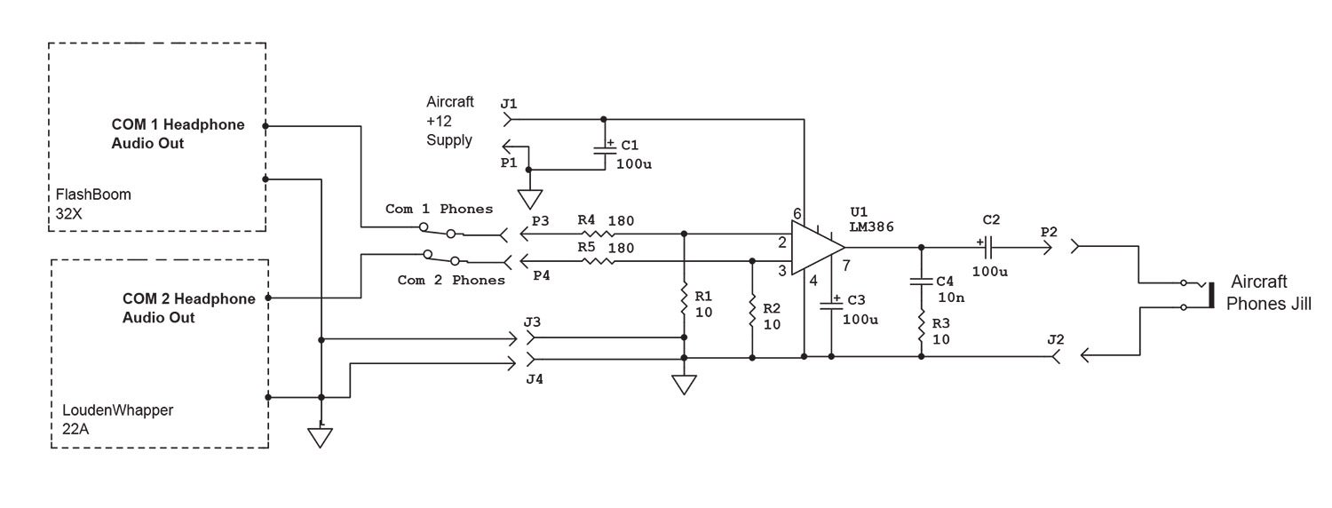
Here is a description of the circuit I would use, but if you decide to go off on a wild tangent, let the rest of us know how it went.
U1 is the LM386. We don’t need all the gain (x20) that this device is set to give, but if for whatever reason someday you need a lot of gain, a capacitor (across unmarked pins 1 and 8) will give up to x200 voltage gain.
C1 is the power supply bypass capacitor to keep pesky engine/battery noise from annoying the output signal (through J1 and P1).
C2 is the headphone’s DC blocking capacitor from the output of U1 while allowing all the audio to go to the headphones (through P2 and J2).
C3 is an additional filtering capacitor to keep any battery noise from the output.
C4/R3 is a hiss filter to keep white noise generated by U1 (if any) from getting through to the output.
R1/R4 is a voltage divider to bring the gain of the entire circuit back to unity (i.e., a volt of audio in for a volt of audio out) on phones channel 1.
R2/R5 Same as R1/R4 for phones channel 2.
If you spend more than $15 on parts for this little circuit for your airplane, please write and let me know how you gold-plated the project.
Until then…Stay tuned…
*The maximum voltage on the high-voltage version of this device is 15 volts. If you have a particularly dirty battery supply, you may wish to consider a bit more filtering of the power supply voltage.


s")


Because COM1 is being applied to the inverted input of the 386, there is a possibility, that if both COM radios are tuned to the same frequency, the audio from each will cancel each other out, and you will hear nothing (or close to it).
Might be worthwhile throwing a decoupling transformer on the inputs from the radios – this then presents a nice consistent impedance to the radios, and you can take the inverted output of one of the transformers to apply to the inverted input of the 386.
As an added bonus, you then get a built-in ground loop isolation function between the radios and the aircraft power supply running the 386.
A single opamp on the input is a hell of a lot cheaper.
JIm
Comments are closed.