So, here we are with fly-in season upon us. And fire season. And lots of reasons to have an aircraft com station on the move to get to the location of interest. Radios move easily. Not so most of our antennas.
Please, whatever you do, do not call that little rubber resistor that came with your handheld an antenna. A piece of limp spaghetti in a copper septic tank would give better results. I’ve done numerous side-by-side comparisons on a plain old single vertical zero gain antenna versus a rubber ducky, and the results are somewhere between -10 and -20 dB of loss on the duck versus the vertical. To translate that to power or range, let’s say we have a 5-watt handheld transmitter with a 1-microvolt receiver. Or if you like, your handheld is trying to talk to an airplane 10 miles away. What is the effect of a simple vertical antenna versus the duck?

A loss of 10 dB on a 5-watt transmitter means that you are actually radiating half a watt (0.5 watts, or 500 milliwatts). A 20 dB loss means that you are actually radiating 50 milliwatts, which isn’t enough power to blow your nose.
On the receive side, that 10 dB loss means that your 1-microvolt receiver is now a 3-microvolt receiver, and the 20 dB loss puts that up to 10 microvolts.
For distance, 10 dB of loss means that 10-mile airplane sounds like it is 30 miles away, and 20 dB puts it 100 miles away.
In either case, you’ve spent a fat chunk of change buying a nice radio with a crappy (that’s a technical term) antenna. Just for bouncing around the airport, that may not seem like a big deal, but if you are actually trying to communicate air to ground at a fly-in or during an emergency, you need something a bit better.
We will do a couple of designs, neither of which will cost you more than a Starbucks Caramel Macchiato Grande ($10). Both of them will be verticals because verticals are what we use for com in the aircraft band. One of them will truly be an in-your-pocket portable, and the other one will fit easily into the luggage space of a C-150 (or tucked into the back seat of a Long-EZ).
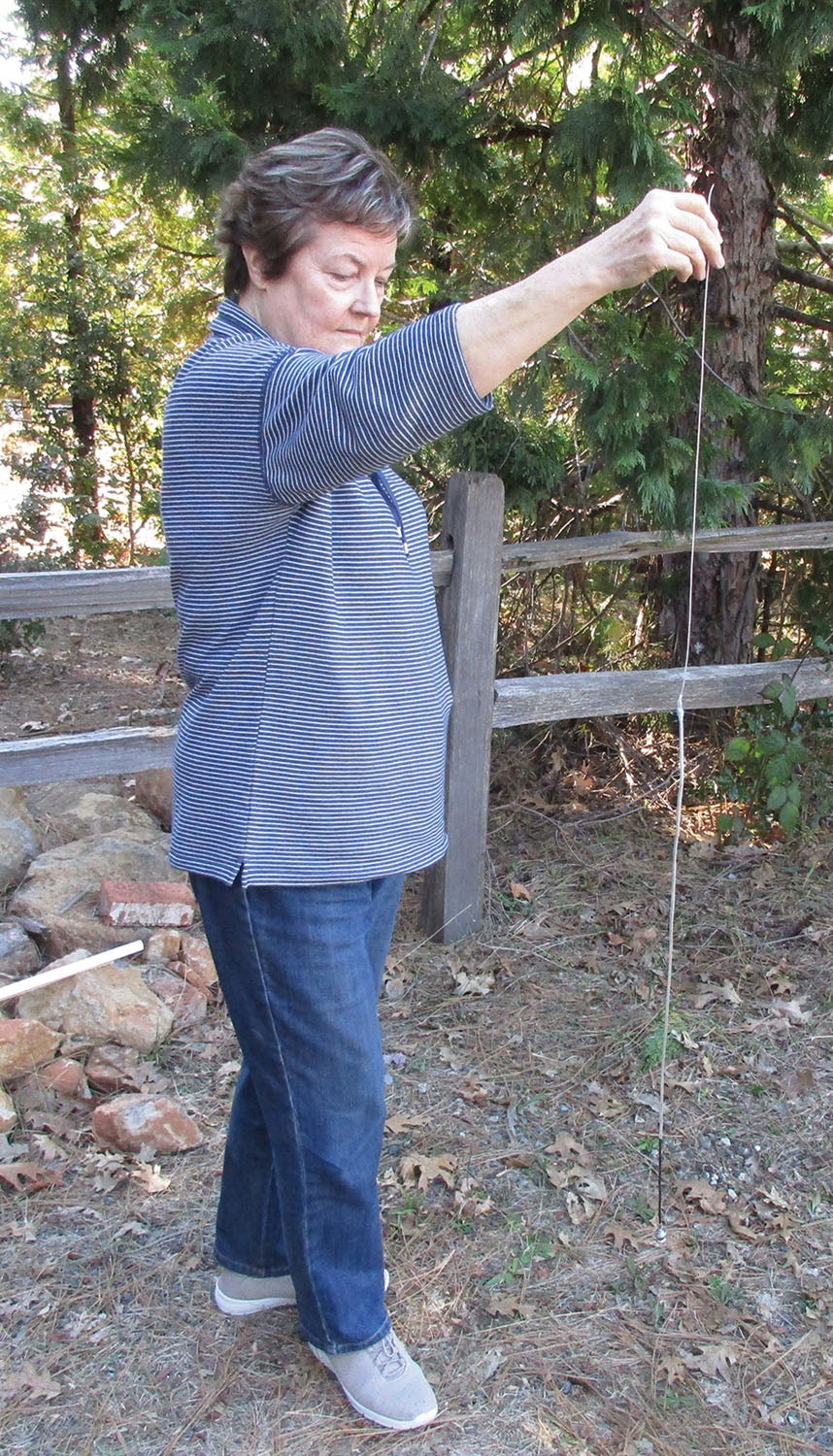
We will also make provisions to haul them up into a handy antenna “mast” like a tree branch or roof overhang. It is true that getting an antenna up into the air and away from the ground makes them perform a whole lot better. So, without further ado, let’s get onto it.
The first thing we need to do is pick our operating frequency since that will determine how long to make the antenna metal elements. I’m going to pick the frequency 122.725 MHz because that’s the frequency of my home drome: Nevada County Intentional Airpatch Unicom. Your frequency might be different, but the difference will be in fractions of an inch from one end of the aircraft com band to the other. And I’m going to do it in plain old eighth-grade arithmetic and not the algebraic notation stuff. All you need is a simple four-function calculator.

Here we go. The speed of light is 186,282 miles per second. 122.725 MHz can be written 122,725,000 cycles per second. Wavelength is speed divided by cycles, or 186,282 divided by 122,725,000 or 0.00151788 miles. Times 5280 feet per mile gives us 8.0144 feet. Times 12 gives us 96.17 inches. See? That wasn’t all that hard, was it? Now, antennas are built on the “quarter wave” principle, so a quarter wave is 96.17 inches divided by 4, or 24.04 inches.
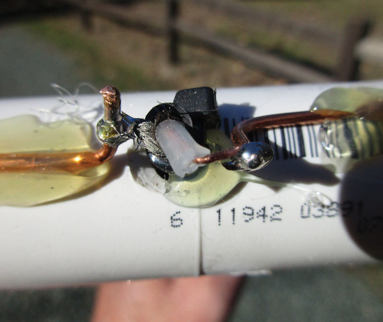
Permit me to add some black magic. For half a dozen reasons, antenna designers start off with a 90% quarter wave when using thin (#10 or smaller) wire. If this magazine were 200 pages long, I’d be glad to explain this phenomenon in excruciating detail, but if you will allow me to hand wave it, this means antenna elements 24.04 times .90 or 21.6 inches long. That’s where we will start. See the images for my antenna tuning tool.
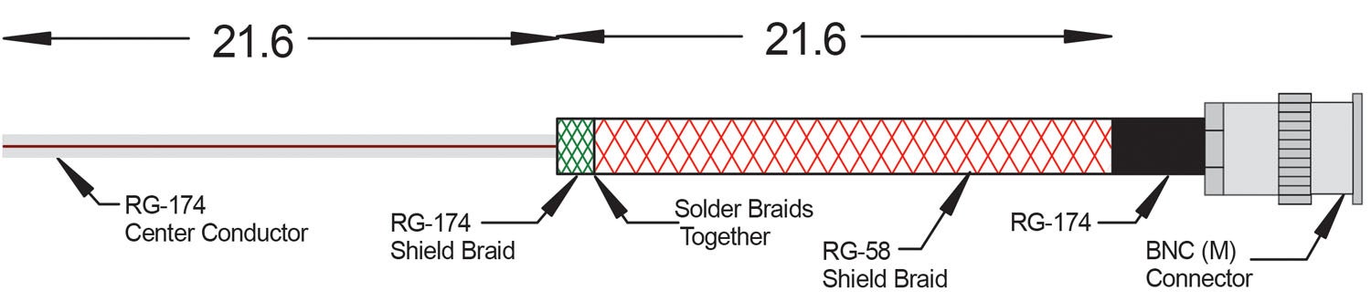
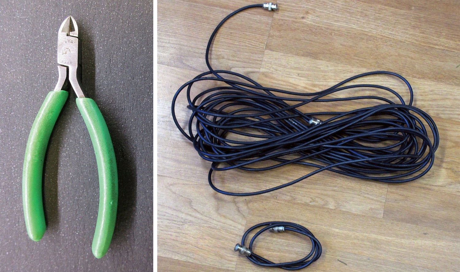
Since this first antenna is going to be shirt-pocket small, we are going to make it out of coax cable shirt-pocket small: RG-174, my coax of choice for anything below 1000 MHz and 10 feet of run. At the com band frequencies it has a loss of 1.5 dB per 10 feet, or a power loss of about 20% for 10 feet. If this is not acceptable, you can use RG-58 with a loss of 10% for 10 feet. Same construction technique.
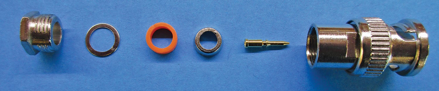
I’m going to take a length of RG-174 coax 72 inches long and a piece of RG-58 24 inches long. Strip 22 inches of the outer black insulation off of the RG-174. Strip all of the outer black insulation off of the RG-58. Cut all but 1 inch of the braid at the remaining black RG-174 insulation. Peel all of the braid from the RG-58, slip it over the black insulation of the RG-174 and solder it to the short 1 inch of braid remaining on the RG-174. Solder the two braids together.
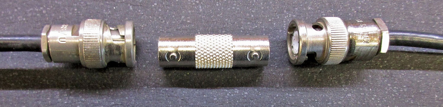
Install a BNC connector onto the 2 feet of coax remaining and tune as described in the second to last paragraph. You can attach the tuned RG-58 antenna braid to the RG-174 black insulation by shrink sleeving or the homebuilder’s perennial favorite adhesive—hot glue.
The advantage to this antenna is that you don’t have to run the coax away from the antenna for a quarter of a wave like you do with a vertical dipole. The disadvantage is that it is relatively fragile and somewhat susceptible to contamination with water and other pollutants over time. It is also a bit more sensitive to being located close to the earth—it likes to be high up.
The alternative is a true vertical dipole with an arm that keeps the feed line away from the antenna. This one is made out of ¾-inch PVC water pipe and Romex house wiring for elements. The cost of making this antenna is 10 times that of the shirt-pocket antenna: $0.10 for the shirt antenna and almost (gasp) a dollar for this one.
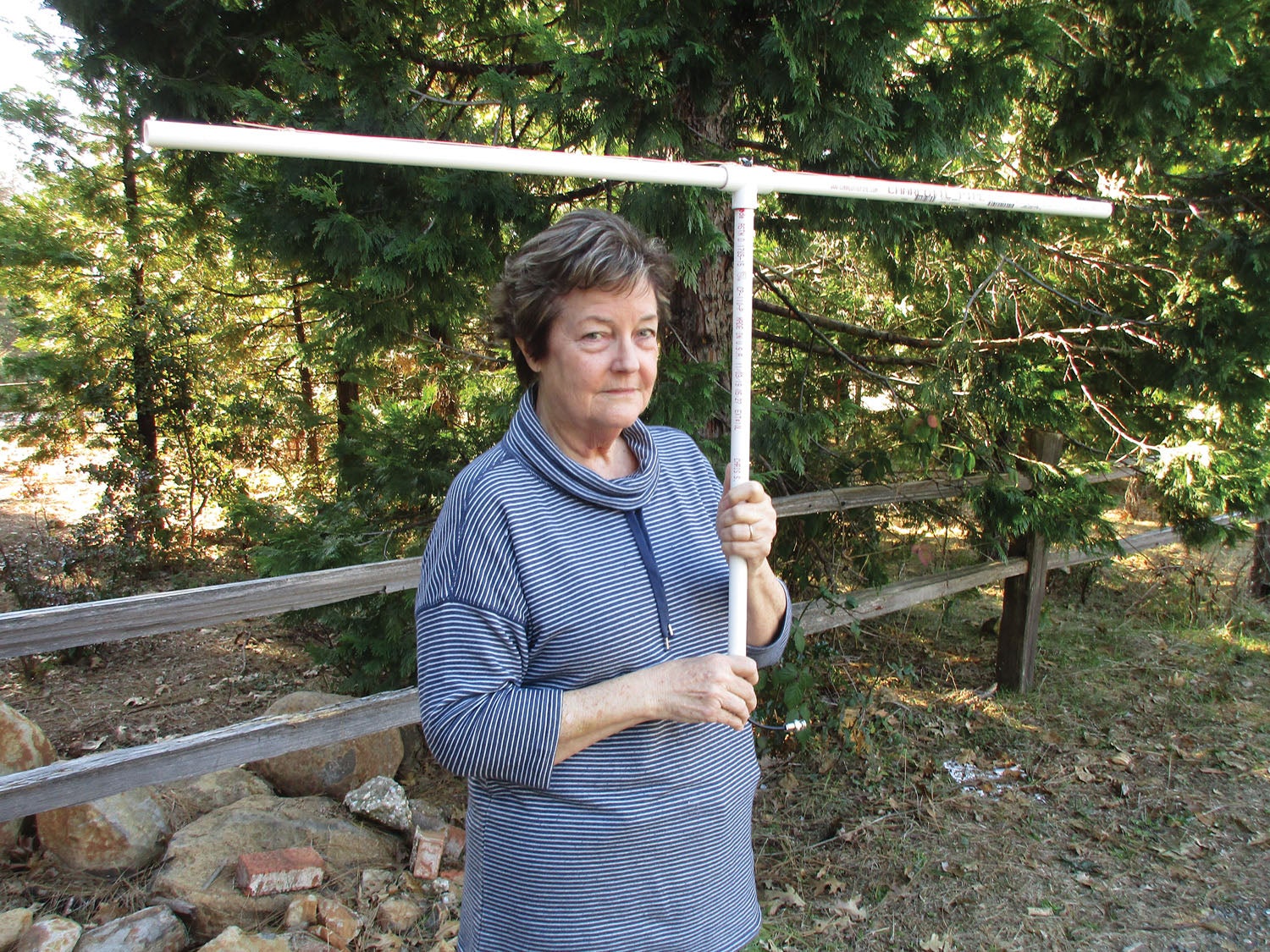
Please note…I’ve shown this design on PVC water pipe, which is what I had in the lab to work with. Cardboard? Plastics? Plywood? Any insulator? Not a problem and no modification necessary.
As with the shirt-pocket antenna, the adhesive of choice to keep the wire onto the surface of the water pipe is hot glue, and the sealant to keep the coax from becoming contaminated is the same hot glue.
Both antennas will work quite well with all of the elements at 21.5 inches long, but if you can get your hands on a VSWR meter, you can prune the antennas to precise length with the tuning tool shown in the images.
There you go, folks, two highly portable antennas for less than $2. Not a bad deal. See you next month, and until then…Stay tuned…
Photos: Jim and Cyndi Weir.


s")


Jim’
A VSWR meter is fine but at the moment You can an antenna analyser with a range till 1000 MHz for less than 50 $
Eddy
Exactly what I was looking for! You gave me a great project and saved me $200!
Comments are closed.