For most people, 10 are enough. Laying out a PC board, you’ve got a few more.
Remember, now, I’m trying to show you the basics of laying out a PC board and condensing a 2000-page manual into four KITPLANES® columns. Or condensing a 90-hour college class to do the same thing. Obviously there are going to be some things that I’m going to have to leave for you to discover for yourself.
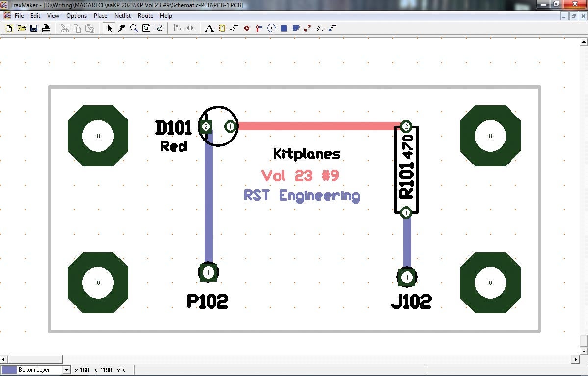
Only one image this month, annotated to show the 12 + 1 commands I’m going to attempt to describe in two pages, so let’s get started (top of the image, starting at the upper left-hand corner).
1. File selects the file commands for the image on the screen. In addition to the usual Windows commands, you get Reports, which gives you a parts listing as well as an X-Y listing of where the part is located on the board. Gerber and NC Drill files are necessary when you send out for manufacture to make dozens of the same board. Print gives a whole bunch of options for printing the board on your laser printer. (You will probably go through an entire ream of paper on your first board try. Don’t worry about it.)
2. Edit > Measure lets you measure the distance between two points on the board. (A later command will let you choose between metric and imperial [“inferior”] forms of measurement.)
3. View lets you see the board expanded in size to fit the window of your monitor.
4. Options > Setup brings up a whole bunch of sub-commands.
a. General
i. Track-Orthogonal means the “tracks” (traces) of copper lines on the board have to be run at right angles, which is the professional way to lay the board out.
ii. Vias (we’ll get to those in a minute) tells me how big the “via” is and what size to drill it.
iii. Cursor Mode lets me set the crosshairs of the mouse commands; my particular choice is to pick the lower-left corner of the “keepout” (more on this later) outline of the PC board to be 0,0 so that all components, holes, pads and lettering are referenced (in mils—thousandths of an inch) to this corner.
iv. Text lets you set the size of a lot of the text that will appear on the board.
b. Layers lets you set the colors of the various layers on the board. We might as well talk about layers right here, as we have given them short shrift up to this point. The board itself generally has at least two layers. A layer is the very thin copper foil bonded to one side of the fiberglass substrate. You can have top or bottom layers on a standard single-sheet PC board. Some very high-end designs can have up to three sheets (six layers) of circuitry, which makes it a real kvetch to troubleshoot because the sheets are epoxied together during manufacture. Don’t worry about it. You will be lucky to get your two-layer board done.
The color does not make a bit of difference as to how the board is made. However, it does make it a bit easier to lay the board out when you can tell top from bottom layers. Historically, the top copper layer is in red, the bottom is in blue and the legend (ink printing) on the top is in black.
Just so you understand, what you see is what you get. You are viewing the board as to how you can see it from the top layer, and the bottom layer as though you have X-ray vision. Through some optical trickery, you will double-mirror the top of the board to match the bottom of the board in the manufacturing stage. Don’t worry about it.
The only layer you may not wish to print or etch onto the board is the keepout layer. Why the author of the program chose this nomenclature is beyond me, because the keepout layer shows all the parts inside of the board—the “keepin” parts. Sigh.
5. Netlist > Show Nets is important. It draws tiny orange lines between points that have to be connected. When you make the connection with a trace (later), the orange line goes away. When all the orange lines go away, your job is done.
6. Route is not for those of us who pride ourselves on having some skill. It simply tells the computer to find a way of connecting all the nets together and makes no attempt to try and keep the board cost down. Yes, it “auto-routes” the board, but it makes a mess out of it. Try to not use it if you can.
7. The capital “A” in the second line from the top simply says, “What text do you want to put on the board, how big do you want it and what layer do you want it on?”
8. The little “squished bug” Component next to the “A” is for your own components that haven’t been given a “package” in the schematic draw process. Sometimes there are oddballs that we don’t want to go through the whole part-defining routine and just want a one-off package.
9. The little stylized “S” next to the squished bug is the heart of the program. It lets you place a track or a trace (same thing) on the board on whatever layer you choose.
10. The brown donut lets you place a pad (hole surrounded by copper) anywhere on the board you wish…say, for a wire that didn’t make it onto the schematic.
11. The red-brown-blue “via” is a way of taking a trace from one layer of the board to another. There are times (lots of times on complex boards) where you are landlocked by another trace on the same side of the board.
12. In the lower right-hand corner of Traxmaker, there is a command that lets you select which layer of the board you are working on. For example, if you want to change a trace from one layer to another, select the layer, go down to the “Layer” command and tell Traxmaker to make the change.
13. Now, a couple of words of wisdom (or been-there, done-that, if you will). Lay the components out. Do a “Netlist > Show Nets.” Move parts around to minimize the number or length of the nets. Save “Jim’s.pcb” to “Jim’s2.pcb.” Mess around with it. Move things, change things, make it better. Save it as “Jim’s3.pcb.” Mess around with it some more. Completely destroy it. Go back and get a prior “good” copy. Try again. Save yourself hours of redo.
I’ve sort of changed my mind. I was going to do the magneto buzz-box for a demo next month. Instead I promised a longtime hearing-impaired reader I’d do a design for him. I’m going to make his board as a demo and then send him the board and components for his airplane, compliments of KITPLANES®. Until then…stay tuned…


")


