Diodes started off life fairly simply. Take an AC signal and convert it to a DC signal. Simple, huh? Then when folks started experimenting with these little rascals, they found that they could be used for a bit more than AC/DC conversion.
One of the slickest uses for a plain old silicon diode (say, for example, the beloved old rectifier diode 1N400x, where x is the rated voltage of the diode) is to use it as a thermometer. A very accurate thermometer. Where, you say, would we need a fairly accurate thermometer in an aircraft?
Just for those of you trying to follow between Fahrenheit and Celsius temperatures, plug these formulas into your Little Golden Book of Cellphone Computers. To convert from degrees Celsius to degrees Fahrenheit, first multiply °C by 1.8 and then add 32. For example, a comfortable room temperature is around 22° C or 72° F.
To convert from °F to °C the conversion is also quite simple—first subtract 32 from °F and divide by 1.8. As above, a comfortable room temperature is about 72° F or 22° C.
The simplest use I can think of is to measure outside air temperature (OAT). We might think of using it to measure cylinder head temperature (CHT). That’s about the limit for silicon diodes. Most of them don’t like much above 400° F (204° C), and even for high-performance engines this may be a bit high. In my experience silicon diodes are much more useful in the electronic engineering lab for measuring transistor heat sink temperatures and the like. Or the temperature of the coffee coming out of the lab coffeepot. Or the temperature of your firewall or the engine baffles in flight.
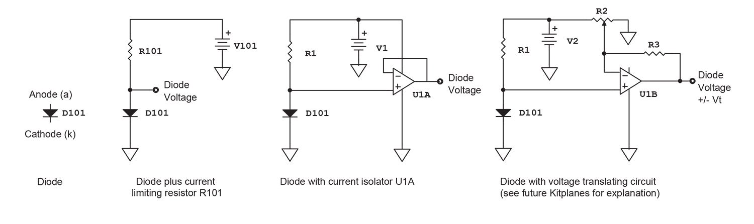
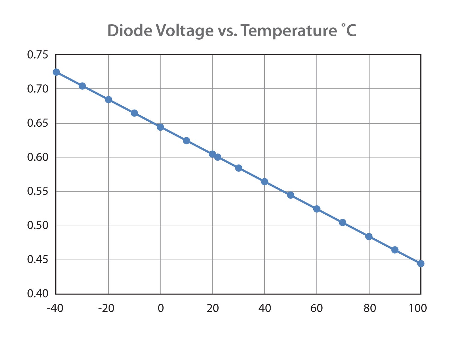
So, here’s the deal: The forward voltage of a silicon diode, biased with some reasonable forward current (say, 20 mA or so), is about 0.600 volts. That is at room temperature, 22° C. For each °C above this, the diode voltage drops about 2 millivolts (0.002 volts). So for a summer room temperature of 32° C, our diode has dropped 20 millivolts, so the diode voltage is now 0.580 volts.
Enter the op amp. And the digital voltmeter. And a cheap current source.
We have presumed a constant current source for the diode, which may well be supplied by a single inexpensive carbon resistor. Let’s presume a reasonably constant voltage, say 5 volts or so, supplied by every USB port and a lot of the digital circuitry we find in current electronic devices. Now we know from the paragraph above that the diode will want 0.6 volts (600 millivolts) of that 5 volts at room temperature. That leaves 5.4 volts to drop from our 5-volt source. We postulated above that our current should be somewhere around 20 mA, so that calls for a resistor (R = E/I) of 270 ohms (270 Ω). Strangely enough, that happens to be exactly the value of a cheap common carbon resistor (2 cents).
Voilà and QED problem solved. Almost. A resistor is only a very crude current source. Any variation in current drawn by the diode (or circuits connected to the diode) will cause errors in the measurement. Same for voltages that may vary as other loads are connected across them. We can do better.
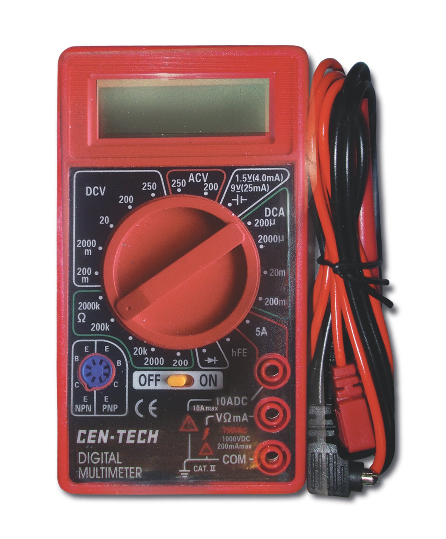
The first and easiest implementation is to use a high-impedance voltmeter to measure the voltage and then use your hotshot cellphone computer to do the conversion of voltage to temperature. My voltmeter of choice (as I have expounded in these columns over the years) is the cheap Harbor Freight digital voltmeter. This particular unit has been my go-to companion for nearly 20 years (in various incarnations as I drop one while working on the rotating beacon on the top of the fin to a concrete floor). Still seven bucks and available every now and again for a free coupon with any other sale. It’s every bit as accurate as the most expensive meter in my arsenal and still runs for about four or five years on a regular old 9-volt battery. While I would never admit it to the feds, there are several dozen aircraft flying today that have had this voltmeter used to repair them. (There must have been a typo in this article to admit this.)
The next easiest thing is to use an old friend of mine, the op amp (operational amplifier) as the current source. While I will reserve all the functions of the op amp to a future issue, using the op amp as a current source and then a calibrator to read out temperature directly is a trivial task.
There are dozens of other diode variants: Schottky, Zener, Gunn*, step recovery*, IMPATT, LED and a few other oddballs that would take me a college semester to share with you. For now, let’s just use the simple, old, slice-of-silicon-with-phosphorous-atoms-implant, garden-variety, silicon diode. (1N4148 et al.) More later. Until then…Stay tuned…
*As you will see in future issues, Gunn diodes can be used to generate microwave energy, and step recovery diodes can be used to make solid-state, instantaneously rotatable microwave beams—both of which I had the opportunity to work with during my first job out of college.


s")


")

![Coming in for a landing at Humberd’s Farm [All Images Credited to Jon Humberd]](https://www.kitplanes.com/wp-content/uploads/2026/07/9-1.jpg?w=324&h=160&crop=1 "Overcoming Setbacks on the Zenith 750SD Xtreme")
