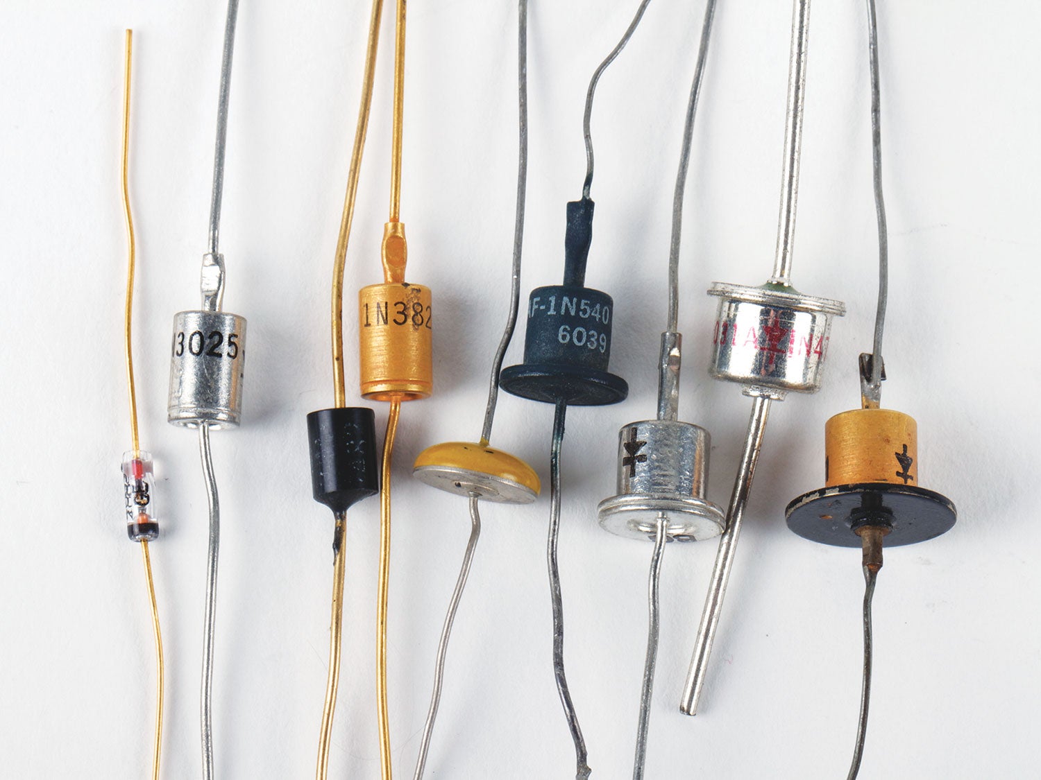
We started talking about diodes last month, those little critters that pass electricity in one direction and refuse to pass electricity in the other direction. Let’s talk about the “yep, maybe, nope” to this general statement.
Before we do that, let’s talk about what makes a diode—what the physical makeup of a diode really looks like on the inside. To do that we first need to talk about silicon. You know, that silvery-gray stuff that Silicon Valley in the southern part of the San Francisco Bay Area is named for?
First of all, silicon is a chemical element, that class of materials that isn’t composed of two or more elements. It is the second most common element in the earth’s muddy crust (oxygen is No. 1). It is about a quarter of the total mass of the earth’s crust. The most common form? Beach sand. Pure silicon dioxide. Next most common form? Quartz. It doesn’t burn. It doesn’t liquefy easily. It is a very stable element. It is fairly easy to chemically split silicon dioxide into fairly pure silicon and oxygen.
The raw material for common diodes is silicon. High-purity silicon. Really high-purity silicon. (Candlemakers, take note). Take a few lumps of silicon the size of a ping-pong ball, put them into a tungsten furnace and heat it to about 2500° F (1400° C). Then take a “seed” of absolutely pure silicon, suspend it from a tungsten wire and dip it into the molten silicon. Let it dry. Dip it again. Lather, rinse, repeat until you have a really pure “candle” of silicon about 4 to 6 inches in diameter. Let it cool completely. Then take a really thin diamond saw and cut yourself a few dozen paper-thin “pancakes” of absolutely pure silicon (called “wafers”). Let them rest back to room temperature.
So far we have produced a paper-thin slice of a perfect insulator of silicon. It is time to introduce a couple more players to the game. Without going into a long song and dance, let me just state that we can once more heat the slice of silicon to near-melting temperature in a box about the size of a laser printer. Draw the inside of that box down to a vacuum and then, using a high-powered electric arc, vaporize a lump of boron, aluminum, gallium or indium. The silicon slice will be “invaded” by these new elements and the trick is to shut the heat off immediately when the invader elements are just a little more than halfway into the silicon. Just for argument’s sake, let’s say what we introduced was “n” type material into the silicon. Now when it is cold, vaporize a thin coat of copper or solder onto the surface of this mix.
Turn the silicon slice over. Repeat the above, but instead of using boron et al., we will use phosphorus, arsenic or antimony. And shut the heat off when this “p” type material is a little more than halfway into the silicon sandwich. The usual coat of copper or solder allows us to attach wires onto both sides of the sandwich of a PIN (p-type, intrinsic type, n-type) semiconductor sandwich. Take the slice of PIN material, slice it up into a million little tiny pieces, and you have the makings of a lot of little diodes. Put a positive voltage on the P side and a negative voltage on the N side and you have a very good conductor. Reverse the battery and you have a very good insulator. Voilà—a diode. Sell them for a penny apiece and you’ve pocketed a grand. Do this ten times a day and the bucks start to add up. Make 10 little furnaces and it really adds up.
What you have done is turned a slice of silicon into a PIN diode. Positive on one end, negative on the other end, with an area in the center where the P and the N have fought to a draw—and left “intrinsic” or pure silicon.
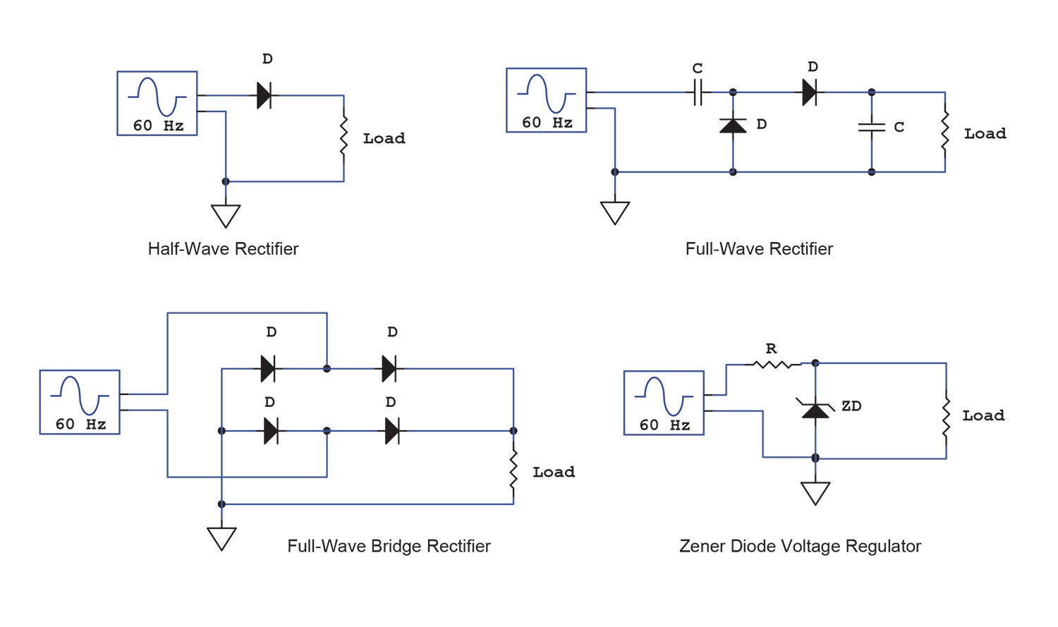
Let’s talk real world. One of the functions of our little diode is to convert an AC signal (whether as a radio detector or wall power) into a DC circuit. We have several ways of doing this.
Simply, we can put the AC (ground referenced) signal onto the P side of the diode (which we now call the “anode”) and the positive side of the AC signal will appear at the N side of the diode (which we now call the “cathode”). This is called “forward biasing” the diode. When the AC voltage reverses itself, the diode is “reverse biased” and is no longer conducting, which gives zero voltage at the cathode. Again, we are in lather-rinse-repeat territory. Put the positive signal on the anode and it appears at the cathode. Put the negative signal on the anode and it disappears. The common term for this is “half-wave rectification.”
That is wasteful as all get-out, throwing half the power away. Enter the “full wave” rectifier.” It takes an input capacitor, an output capacitor and another diode. But now you get both halves of the input wave as output—direct current.
There is another trick up our sleeves if we don’t want to introduce a capacitor into the equation and the input signal is not ground-referenced—say, from a transformer or coil combination of some sort. It is possible to provide full-wave rectification as well as ground-referencing the signal by using a full-wave bridge rectifier. Output is still both halves of the input AC wave, but now it is ground-referenced.
I lied to you. I told you that a diode only conducts in the forward bias direction. That is true, up to a point. A genius named Clarence Zener noted that almost all diodes have some reverse voltage limitation that prevents them from being used on relatively high-voltage circuits because they “break down” and become total conductors when reverse voltages above the “Zener voltage” is applied to them. Investigation of how diodes are “doped” with p and n materials led Zener to the discovery that almost all silicon diodes can be fed their p and n “dopants” in a concentration that allows them to break down in the reverse direction, all the way from a couple of volts to hundreds of volts.
“Zeners,” as they are called, are used in nearly every electronic device on the market today as voltage regulators. Supply them a minimal amount of current and they will maintain their Zener voltage over a wide range of currents.
There are several dozen variants of diodes that have been developed over the years, including a few that I really can’t discuss. It has been 50 years since I’ve been involved with them, but I think I can tell you without violating my TS clearance that if it weren’t for a particular variety of microwave diode, Apollo 11 would have had a really difficult time landing on the moon.
More next month. Until then…Stay tuned…


