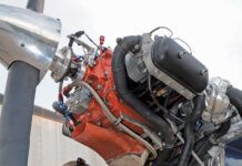
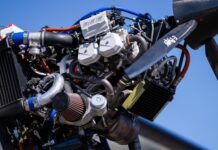
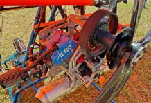
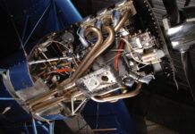
Lycomings four-cylinder engines are the most popular engines installed in kitbuilt airplanes. While carburetors used to be the fuel mixer of choice, mechanical fuel injection has been gaining popularity-it is now price competitive and better performing (particularly if you intend to run lean-of-peak EGT mixture settings). The most common system is the Bendix/Precision RSA. We use the slash here because Bendix developed the system in the 1950s, but the rights and production now belong to Precision Airmotive in Washington state. (Incidentally, as you read this, Ill be in Spartanburg, South Carolina, learning more about the alternative Airflow Performance system. Look for a report in a future issue.)
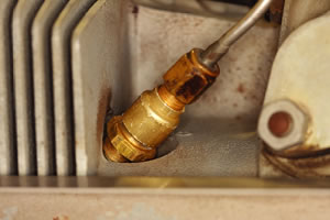
The modern Bendix-style injector has a replaceable insert. Be very careful torquing the injectors into the cylinder head.
The heart of the RSA-type fuel-injection system is the fuel servo unit-sometimes known as the servo regulator. Its bolted onto the air-in end of the engine, and is in unit with the throttle body. Continentals mechanical injection separates the throttle body and fuel-metering units, which is why I make the distinction.
Fuel flows in through a fine screen at the fuel inlet to the fuel-control portion of the unit. The needed fuel flow/mixture is controlled by the movements of air and fuel diaphragms that constantly sample and adjust for changes in inlet (ram) air, venturi air pressures, and unmetered and metered fuel pressures. These diaphragms control movement of a shaft that opens or closes a ball-type servo valve, controlling the fuel flow to the engine.
Fuel flows out of the servo regulator through a flexible insulated hose to a flow-divider assembly mounted on top of the engine, and then out through stainless-steel lines to fuel-injection nozzles at each cylinder. The flow divider does three things: It evens out the idle, distributes fuel to each cylinder and aids in a clean shutdown of the engine.
Idle Speed Adjustment
Follow these steps to set the idle speed (before attempting to set the idle mixture):
The engine must be at operating temperature. Running the engine for short periods on the ground is not sufficient.
- Pull the throttle back all the way, and look for an idling rpm between 600 and 650.
- If the rpm isn’t within this range, visually check to see if the idle speed screw is hitting the low-rpm stop on the servo body. If it isn’t hitting the stop, there’s a rigging problem. Either the connection between the throttle control and the fuel servo arm needs to be re-rigged to obtain full travel to the low and high rpm stops, or the connection needs to be re-rigged because the cockpit control is hitting its internal stop before the fuel servo arm hits its stop.
- Re-rig as necessary to ensure that the throttle on the servo moves freely from low to high rpm stop before the cockpit control hits its internal stop.
- Adjust the idle-speed screw (located on the throttle shaft adjacent to one end of the idle mixture adjustment linkage) as required to obtain a 600 to 650 rpm idle. Your mnemonic for adjusting idle speed is: Screw IN for rpm INcrease.
Idle Mixture Adjustment
The idle-mixture adjustment assembly consists of an adjustable-length linkage between the throttle butterfly shaft and the idle valve lever thats attached to the fuel-control portion of the servo regulator. Turning the thumbwheel one way shortens the link, richening the idle mixture; turning it the other way lengthens the link assembly, leaning the mixture.
Follow these steps when setting the idle mixture:
- The engine must be at operating temperature. Making the adjustments after a flight is the best way to ensure the engine and fuel-injection system are up to temperature.
- Pull the throttle back against the low rpm stop. This should result in an idle rpm of 600 to 650 rpm. If pulling the throttle back against the low rpm stop doesn’t give this result, adjust the idle speed until it does.
- With the engine idling, slowly pull the mixture control out. Pay particular attention to the rpm and the sound of the engine just before it dies. When the idle mixture is correct, the rpm will rise slightly to between 25 and 50 rpm. If the mixture is too rich, it will rise more than 50 rpm; if the mixture is too lean, it will not rise at all.
- Make an adjustment, and then run the engine up to 2000 rpm for a few seconds to restore fuel flow through the fuel-injection system. Then reduce rpm to idle speed before conducting the idle mixture test again. If the R and L on the thumbwheel aren’t visible, your mnemonic for adjusting the mixture is: Longer is richer.
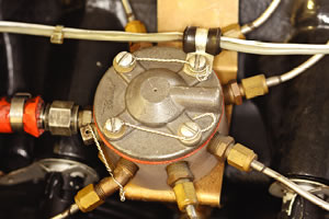
The flow divider does more than distribute fuel to all the cylinders; it contains an anti-drip valve to keep fuel from seeping into the engine and to provide a clean idle cutoff.
Cleaning Nozzles and Screens
Precision Airmotive recommends cleaning injector nozzles and fuel control fuel inlet screens every 100 hours or at every annual, whichever comes first. Don’t ignore the fuel-inlet screen-Precisions DVD titled Maintaining the RSA Fuel Injection System recommends cleaning the inlet screen every 50 hours. The RSA fuel-injection system supplies a constant flow of fuel to the flow divider and then out to the injection nozzles, which are screwed into the aluminum cylinder heads. When the mixture control is pulled back to stop the engine the hot cylinder heads throw off enough heat to boil the fuel in the stainless-steel fuel lines that run from the distributor valve to the nozzles. The lighter components of the fuel evaporate, but the less volatile constituents of the fuel cook down to a varnish. When the varnish layer gets thick enough, fuel flow to the cylinders is restricted.
Follow these steps when cleaning nozzles:
- Carefully back off the nut at the cylinder head end of the stainless-steel fuel line and slide it up the line out of the way. Gently move the line to permit access to the injector.
- Injector nozzles made after 1981 have two pieces. Remove the inner piece (the restrictor) from each injector. Always return the restrictor to the nozzle body whence it came. Do this by putting each restrictor in a separate bottle thats marked with the cylinder number. Do not string wire or string through the restrictors. Pre-1981 injectors are of one-piece construction. They must be unscrewed from the cylinder head for cleaning. During reinstallation, torque the injector to 40 inch-pounds and then tighten as necessary to ensure that the symbol-usually an A-on one of the hex flats points within 30 of downward. This will align an air-bleed hole so it points up. (See Lycoming Service Instruction S.I. 1275C.)
- Soak the restrictors or injectors in Hoppes #9 Gun Cleaning Solvent for 20 minutes, or methyl ethyl ketone (MEK) or acetone for one hour. All of these cleaners are available at hardware or building supply stores. MEK is an extremely hot cleaner; even one sniff of this stuff causes brain drain, so preferably go with Hoppes or acetone. After soaking, rinse the nozzles in Stoddard solvent and blow-dry with compressed air.
Idle mixture, and to some extent idle speed, are not static. Plan on fine-tuning the idle mixture at least twice a year due to seasonal climatic changes, after cleaning injection nozzles and after work on one or more cylinders.
Troubleshooting: You Love It!
If the engine still doesn’t start easily, idle smoothly, accelerate without hesitation, develop full power, or if it exhibits a stumbling or incomplete shutdown after completing the idle speed and idle mixture adjustments explained above, or if the idle speed and idle mixture values cant be set, further trouble-finding procedures must be carried out.
Typical RSA problems often include:
- One or more clogged fuel-injection nozzles, causing a power loss and a higher-than-normal fuel flow indication for pressure-gauge flow meters.
- Rough or incomplete engine shutdown caused by a scored mixture control jet or rotating plate, or by a scored piston or dirt on the valve seat in the flow divider. A clogged bleed hole in an injector will also cause a rough shutdown.
- An exceedingly rich mixture caused by internal leak in the regulator section of the servo-regulator, permitting fuel to travel from the fuel side into the air side of the regulator where its sucked into the air-induction system. One symptom of this fault is the need to lean the mixture on final or after landing to prevent the engine from stopping.
- High cylinder head temperatures that can be caused by restricted fuel nozzles or the wrong fuel lines (primer lines look similar but are much smaller internally).
This list is not meant to be comprehensive. These RSA fuel-injection system faults as well as tests for trouble-finding are detailed in Precision Airmotive training and troubleshooting manuals. They are available online: The Precision Airmotive RSA Training Manual is at http://www.precisionairmotive.com/Publications/15-812_b.pdf; the Precision Airmotive RSA TS Manual is at http://www.precisionairmotive.com/Publications/15-810_b.pdf.

![]()
Steve Ells is what you call a gen-u-ine mechanic, a bonafide A&P with an Inspection Authorization. Former West Coast editor for AOPA Pilot and tech guy for the Cessna Pilots Association, Ells has flown and wrenched on a wide range of aircraft. He owns and wrenches (a lot!) on a classic Piper Comanche. But don’t hold that against him.

