Welded assemblies (also known as weldments) can be found on just about every airplane. Even my Jabiru, which is 99% fiberglass, has a tubular-steel welded engine mount and welded rudder pedals. Most weldments start out as fabricated components designed to be welded. But some, such as the carburetor cable bracket shown here, don’t start out with the intent of becoming a welded assembly. In this case, the original design didn’t work with the particular airframe and engine mount, but welding provided an expeditious and reliable solution to facilitate the changes required.
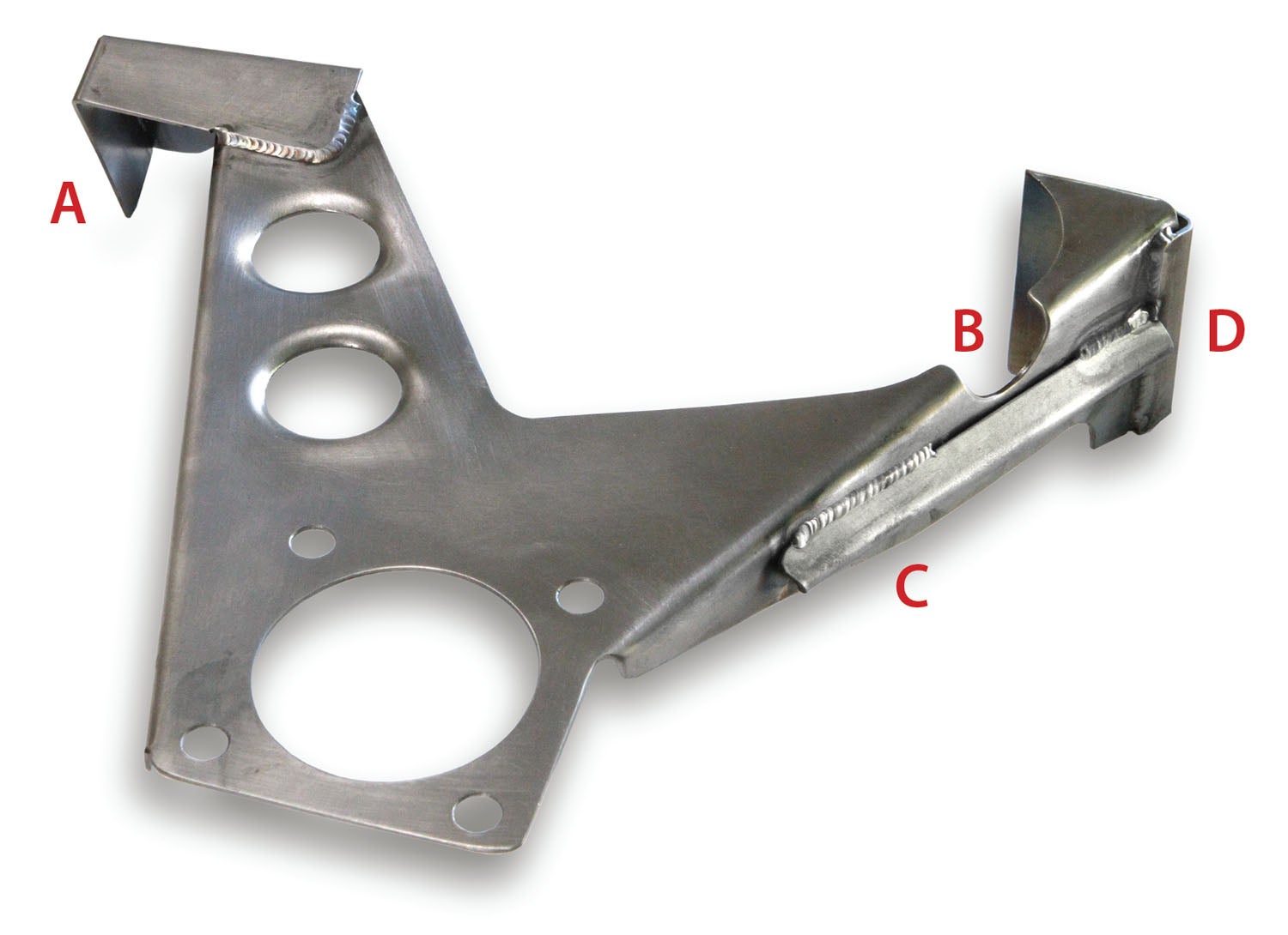
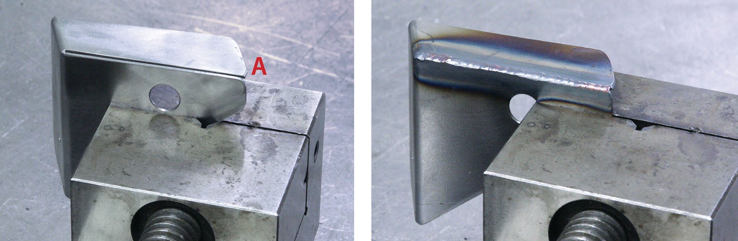
During the initial fit-up of the bracket to the engine on the airframe, it was clear that both extensions needed to be modified. On the mixture side (A in the photo), the stop had to be completely removed and a new tab with more offset needed to be welded on. On the throttle valve side (B, C and D), a cutout was needed to clear a lower engine mount support. This cutout (B) bisected the reinforcing flange, which compromised the rigidity of the original design. The solution was to add an edge gusset (D) and a longeron V-brace (C).
The new tab and braces were relatively simple to make using a pan and box brake. After a trip to the airport to double-check the fit and clamp the pieces in place, it was back to the shop for welding.

My go-to guy for welding is TIG-master Billy Griggs. Billy has done a number of welding jobs for my airplane projects, including a landing gear strut and a set of stainless exhaust headers. In addition to being an expert welder, Billy is also a great teacher (he once gave our EAA chapter a TIG welding demo). I figured this sheet metal bracket was about as simple as could be. But, in typical teacher fashion, he grilled me with questions like “What is this for?” and “How much stress and vibration will it see?”
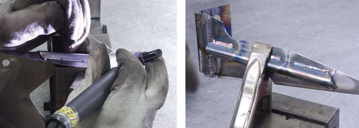
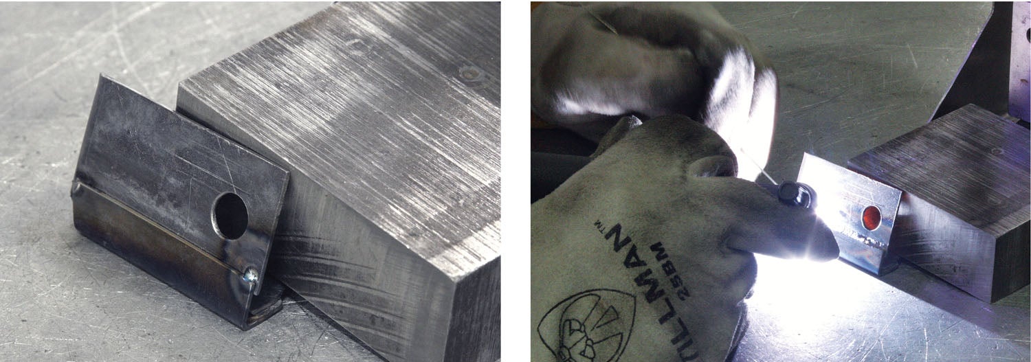
As I filled in the answers, he nodded and went on to explain how important it is for a welder to understand how and where the end product will be used. Thin sheet metal parts tend to warp during welding, so how they’re clamped, tacked and welded can have a major impact on how much they warp. Although this bracket is not subject to a great deal of force, it’s attached to the engine, which means constant vibration and heat. Billy suggested I radius the edges on the tabs where the welds start and finish, and that he’d put a bead on the inside of the mixture tab to prevent the two parts from levering against each other. The concern was, if that bead was not there, that joint would be the most likely failure point. The filler rod Billy selected for the job was 0.035-inch diameter Weld Mold 880. Although this type of rod is expensive, it is ideal for jobs on crack-sensitive materials, such as sheet metal.
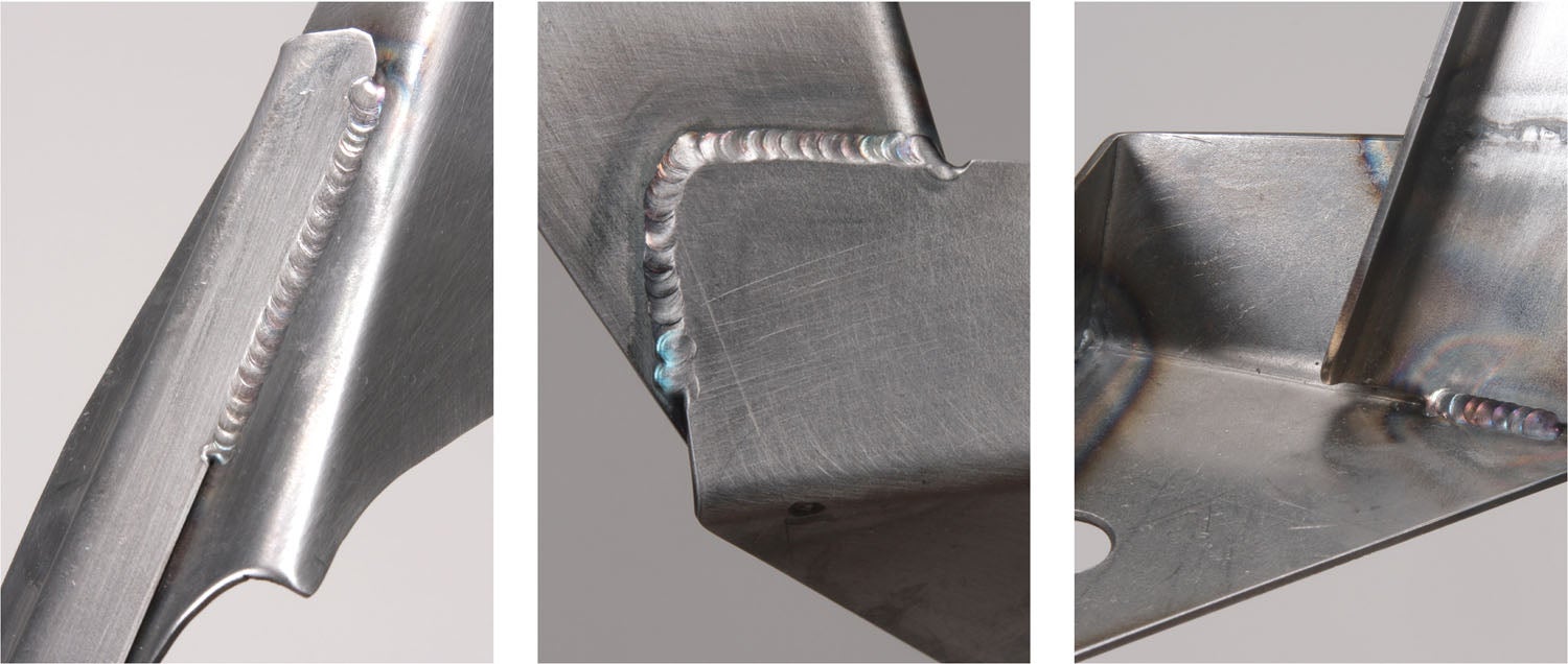

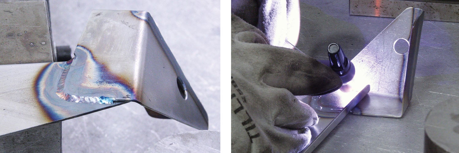
Another technique Billy used to minimize distortion was to stitch weld on the longeron brace. This is a technique where instead of a continuous weld the full length of the seam, sections are skipped over to reduce heat exposure or to avoid welding too close to an edge.
That’s it for now. Time to get back in the shop and make some chips!
Photos: Bob Hadley.


