
Freely admitted, my very early experience with antennas was confined to looking at a newspaper picture of Sputnik 1 (Prosteyshiy Sputnik-1) in October 1957 and figuring out as an eighth grader that it was beep-beep-beeping somewhere around 20 MHz. That was pretty obvious from Russian news clips of the antenna lengths.
How did Sputnik 1 get an antenna long enough to be “resonant” on 20 MHz and be stuffed inside that grapefruit-sized satellite? The math shows that to be resonant, the antenna needed to be about 150 inches long and be straightened once in orbit. Pretty simple. A 12-foot metal tape measure coiled up inside the satellite will do just fine once uncoiled in orbit, thank you.
My neighbors that I invited into our house to listen to those beep-beep-beeps of the satellite on my roof-mounted surplus Romex wire antenna and junk-TV-tubes receiver must have tipped off somebody because this 12-year-old Catholic-school eighth grader got a visit from the San Diego FBI to see what sort of mischief I was up to. They used an antenna analyzer truck to measure my antennas—anti-Russian paranoia of the 1950s run wild (see the movie, October Sky).
There are three major things we worry about when we analyze or build antennas. One is the input impedance of the antenna, to figure out how to match the transmitter or receiver to the antenna. Another is the antenna pattern—how much energy are we squirting out and in what direction? The third is the polarization of the antenna; is our signal bouncing up and down or left and right (or some oddball angle in between, or even continuously rotating)?
I think it is OK if we just worry about the first one right now: What is the input impedance of the antenna?
As I said on several occasions, it is most unfortunate that our ancestors chose to measure impedance in ohms (Ω). That implied (at least to me, once upon a time) that I could simply take a DC ohmmeter in my multimeter and stick it on the antenna to read the impedance, which is not true. Why they didn’t use “squirds” or “veeblefelsters” or some other cockamamie word is beyond me. I mean, Georg Ohm, Allesandro Volta and Andre Ampere all got their names into the record books. Why don’t we measure impedance in Marconis? Or Yagis? Or (blush) Weirs?

Let’s start off with wavelengths. We are all familiar with miles per hour. If my aircraft is traveling at a ground speed of 150 miles per hour, how long does it take to go 10 feet? Well, 150 mph = 150*5280 feet per mile = 79,200 feet per hour. Or (divide by 60) 13,200 feet per minute. Or (divide by 60) 220 feet per second. Which is 0.0045 seconds per foot (1/220). OK, if it takes 0.0045 seconds (4.5 milliseconds) per foot, then it should take 10 times that to go 10 feet…0.045 seconds (45 milliseconds). A very small number, but easily calculated if a bit laborious to get to the answer.
And we’d do things a lot faster if we could work in metric kilometers, but except for NASA space work done in metric, only the United States and Liberia are on the Imperial (British foot-pound) system of measurement. I thought we got rid of that British stuff in the War of 1812. But I digress.
What does all this have to do with antennas? It turn out that antennas like to be some very small fraction of the speed of light, which is the same as the speed of radio waves. And I’m going to aim my discussion at those of you with an $8 “engineering” calculator from Walmart. In calculator-speak E3 means 103 = 1000, like 186E3 means 186,000 in the “ENG” function of the calculator. E-3 means /1000. And 0.0045 (in the example above) is 4.5E-3. And note well that all engineering prefixes are in multiples of 3 (3 = kilo = 1000, 6 = mega = 1,000,000; -3 = milli = 1/1000, -6 = micro = 1/1,000,000) and so on.
So, here we go. There is magic in a quarter-wavelength of a particular frequency of interest. And let’s get some constants defined. The speed of light/radio is 186,282 miles per second (186.282E3). In inches (which we are going to be using to lay out our VHF antennas) that’s 11.802E9 inches/second. Now we have a VOR nav signal from a ground station on 113.0 MHz (the center of the nav band), and we ask what is a wavelength at that frequency? 11.802E9 / 113.0E6 (Mega = E6), we find that a wavelength is 104 inches. Or 26 inches for a quarter-wave.
Now for the practicals. Any wire antenna has what is called “end effect,” which is generally considered to be 5% shortening. That takes our 26-inch antenna down to 24.8 inches. That is for an infinitely small wire. But most of our antennas are made out of sterner stuff. In particular, a small diameter (AWG 14, 0.08 inch or so) may be only 3% smaller, while a fat (1/2-inch) copper tape antenna may be 8% smaller. There is a very precise way of making this calculation, called an X-Acto knife procedure. Cut the antenna until you think it needs just one more little piece trimmed off, and don’t take it.
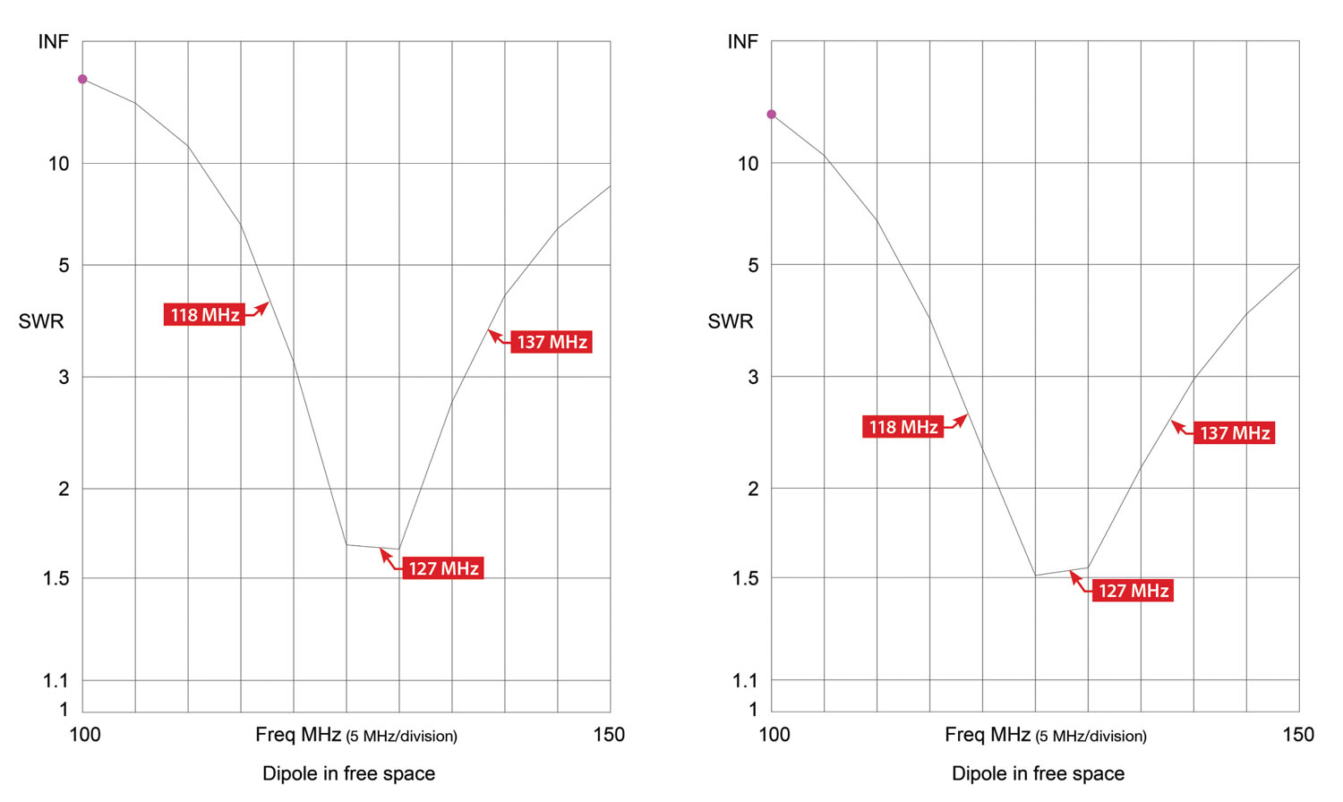
Or you can use what is called a VSWR meter (pronounced VIZZ-war) on the antenna. VSWR (voltage standing wave ratio) is simply an engineering term that means “how close to perfect is your antenna matched to your radio?” In the radio world, we use 50 ohms as the standard, which is halfway between a perfect dipole antenna (72 ohms) and a perfect vertical antenna over a ground plane (32 ohms). So neither antenna can be a perfect VSWR of 1:1 but will always be about 1.5:1. No big deal.

So what does VSWR do to you? It reflects any signal or power back down the transmission line and does not deliver it to or from the antenna. How much? 1.5:1 VSWR means about 5% of the power (or signal) gets bounced back down the coax. Five percent isn’t that big of a deal. But what happens when we go to the ends of the band instead of the middle? 2:1 VSWR is a 10% power loss and it just gets worse from there. I’ll show you the calculation next month on how to easily calculate the loss.
So, how can you get your antenna down to a lower VSWR? There is only one simple answer: Make it fatter. If you are making a plastic airplane, use wide (1/2 inch) copper tape or some other low-resistance conductor instead of thin wire.
More antennas, more solar hangars, and more general avionics floobydust later.
Until then…Stay tuned…


