 A friend at my airport confessed to having some avionics problems. His homebuilt’s instruments include a Garmin G5 for a primary instrument, a BendixKing (nee TruTrak) xCruze 110 autopilot (with integrated attitude display), a Garmin digital nav/com and an aera 660 GPS to provide position information. He complained of sporadic dropouts of the RS-232 nav signal going to the G5—it’ll issue a warning on screen if that data source is lost—and the autopilot acting oddly. He enlisted my help to troubleshoot. I’m familiar with all of these boxes, so how could I say no?
My first thought was that there could be a data mismatch, though the on-again/off-again nature more suggested a partially broken wire or a pin coming out of a connector somewhere. I asked the owner for the wiring diagram. To my surprise, he didn’t have one. He asked the avionics shop that did the installs—he’s not the builder of this airplane and elected to let the pros do the work—but after some delay they responded with a dismissive, “We didn’t do a diagram because it’s a simple system in an Experimental,” or words to that effect.
OK, so I’m starting from square one. Like many of Garmin’s handheld GPSes, the aera 660 has two serial channels available when installed with the aviation mount and bare-wire harness. Fortunately, the G5 has a feature showing whether connected data lines are working by showing either a green check or a red X; green means it’s communicating properly, red not so much. Because I had no documentation, I had to guess at the physical configuration. How is the aero connected to the G5 and the autopilot? Which ports are in use? How are they supposed to be configured? All questions without a ready answer because of a lack of documentation.
By working through all the possible combinations of data type and baud rate (on both serial lines from the aera) and watching the G5, we were able to determine that the G5 wasn’t seeing the RS-232 data. We restarted all units and tried again. Nothing. Not only that, but the xCruze confirmed that it wasn’t seeing the GPS data, either. (Cleverly, the track display changes colors to indicate what kind of GPS/position data it’s seeing.)
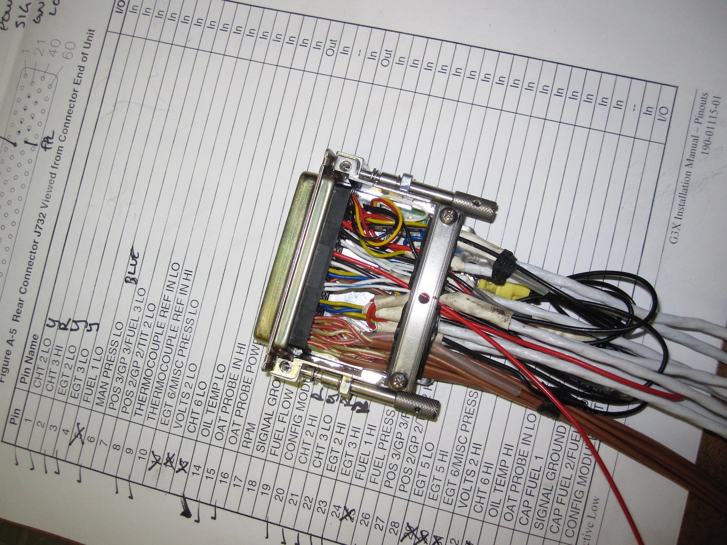
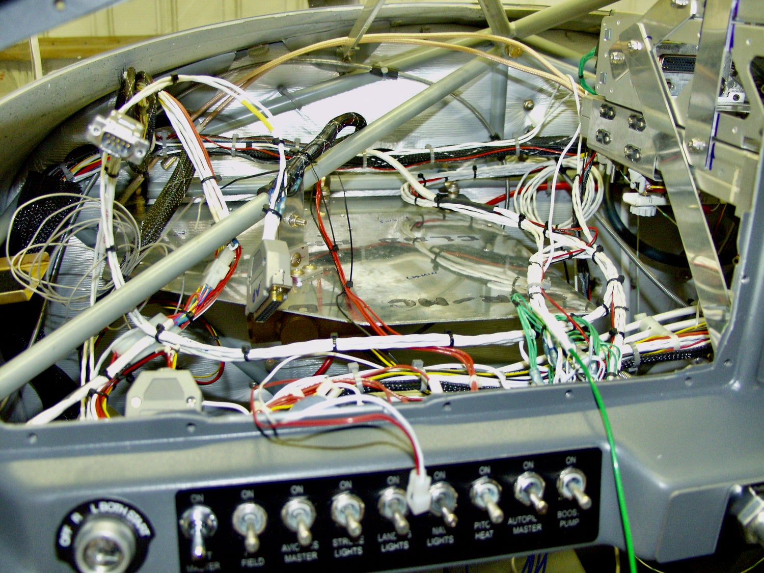
So now it was a matter of tracing the wires, not an altogether easy task on this small homebuilt. I was lucky enough that the power and data wires from the G5 were visible and not bundled with something else. From that, I could tell the aera was connected directly to the G5’s single RS-232 input without any interconnections. How, then, did the autopilot get its needed GPS reference? To learn the answer, I had to pull the AP head and take apart the connector back shell, only to discover the wire connecting to the TruTrak’s RS-232 input disappeared into a large and tightly bundled wire set. Without documentation, I had no idea where the other end was connected. To the Garmin GAD 29 ARINC 429 converter? Nope, no serial outputs there. To the second serial output from the aera GPS? Nope, it was bare.
How the heck was this thing wired? One clue came from the owner who said that the autopilot was never able to follow a flight plan on the GPS. I know from experience that even a simple GPS like the aera 660 will output a flight-plan sequence that the TruTrak can fly, if properly configured and connected. From that I deduced that the TruTrak was never connected to the GPS in a meaningful way. Another hour running a replacement RS-232 connection from the aera’s second serial output to the autopilot did the trick, though I was careful to tie off (and not clip) the existing serial wire in case I’d broken some other functionality. Again, this was more a hope than a certainty given that no one had written down what was connected to what in the particular airplane.
The avionics shop that did the work might just say to follow the examples in the manuals. All well and good but that doesn’t help when your specific example isn’t in the books at all. In fact, the TruTrak manual gives examples of how to directly connect to a GPS source, either panel mount or portable. This airplane wasn’t set up in any way resembling these suggestions.
In the end, connecting the TruTrak to the aera 660 directly gave it a more reliable signal and the ability to follow course guidance, proven by test flights. The original problem? Caused by a bad splice between the aera’s harness and the wire leading to the G5. A simple mechanical problem. One that would have been much more easily understood with a wiring diagram to weed out other possibilities.
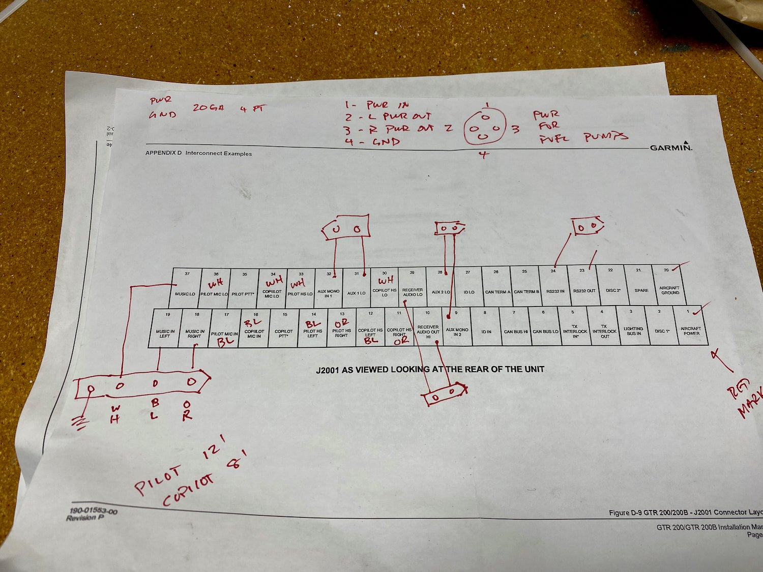
The point is this: Even basic documentation can help make troubleshooting simpler and faster, either for you (whose time is very cheap) or the avionics shop (whose time isn’t.) It doesn’t have to be elaborate and can be greatly assisted by cogent marking of wires and bundles in the airplane. Think about the next person working on the airplane you build.
![[Credit: JetStream Rider]](https://www.kitplanes.com/wp-content/uploads/2026/04/AdobeStock_345999332.jpg?w=218&h=150&crop=1 "2026 Avionics and Lights Buyer’s Guide")
![[Credit: Dynon]](https://www.kitplanes.com/wp-content/uploads/2026/04/EMS-stand-alone_HDX.png?w=218&h=150&crop=1 "Dynon Unveils Scalable Engine Monitoring for Kitbuilders")


I’m using Qelectrotech. It’s free/open source. Runs on Windows/Mac/Linux. Allows generating various lists and is fairly simple to use.
It’s designed for multiple disciplines so it’s great for documenting Pitot/Static, Fuel, and other hydraulic items such as brakes/ landing gear.
Point to point wiring diagrams are the hard way to document avionics. The more useful information is which port on which device is connected to which port on the other device, and what the port settings are at each end — the settings don’t always have the same name! I put all this information in a spreadsheet, with the layout of the settings matching the layout of the device screens in configuration mode. I then made a pdf and put it on the cellphone, in case I need the data in the field. With the ports identified, it’s easy to get the pin numbers if ever required.
I used a combination of xfig for block diagrams (I converted everything to dia after a couple years) and a simple spreadsheet.
I labeled each end of each wire with numbers. The spreadsheet wire label was the first column, a description of the circuit it was for was the second and third column.
The positive wire was the number, the ground wire was the number with an “A” suffix. I used other suffix letters for reverse circuits and such.
Dia was used for building connector diagrams as well. Each pin could be numbered and lettered and a tab in the spreadsheet could follow those.
http://dia-installer.de/
Comments are closed.