 In the logical way that I approach a project, I would expect to build an airplane in a way that follows the manuals, from A to Z, in an order that is from beginning to end for the entire build. But that is not the way the manuals are arranged for the RANS-21 Outbound. Following the directions, we will leave a large section of the wing build undone for now—that includes the fuel tanks, attaching to the fuselage and attachment of flaps and ailerons—so that we can skip to the tail cone/fuselage build. There is a bigger plan, that much we’ve learned.
Before we move on, though, it may be useful to review the S-21 design so what follows makes more sense for anyone joining this build at Part 5. Up to now, we’ve been dealing with overall organization and shop prep, which I hope was useful to many of you, and then we moved on to the tail surfaces followed by the wing and controls. On the S-21, these are conventional aluminum construction using mostly traditional design features, though there are blind rivets—call them “pop” rivets if you want, but they’re aircraft grade—and some clever deviations, like the closely spaced front spar/D-section that makes up the lightweight leading edge of the wing.
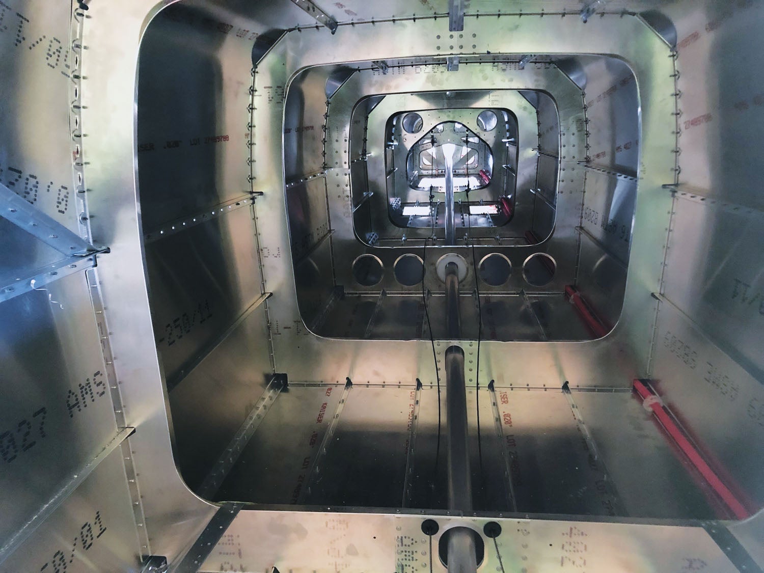
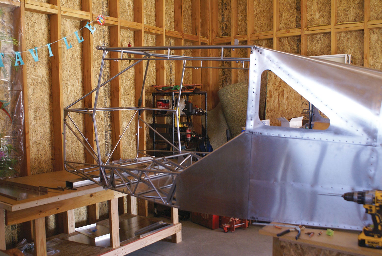
But now we’re on the tail cone or empennage, if you’ll pardon my French, and here I should probably clarify a bit more. The S-21 is not like a Van’s design, where the fuselage is basically one large aluminum “canoe” from the firewall to the tail. In fact, as I understand it, the S-21 is more like an aluminum GlaStar or Sportsman. Around the passengers is a steel-tube cage, provided complete by the factory. It connects the engine mount ahead of the firewall to the wing spars, the landing-gear attach points and the lower strut fittings. The empennage rivets to the back end of the cage to encapsulate the baggage area and carry the structural tail loads. And that cone is the focus of this installment.
OK, Back to the Build
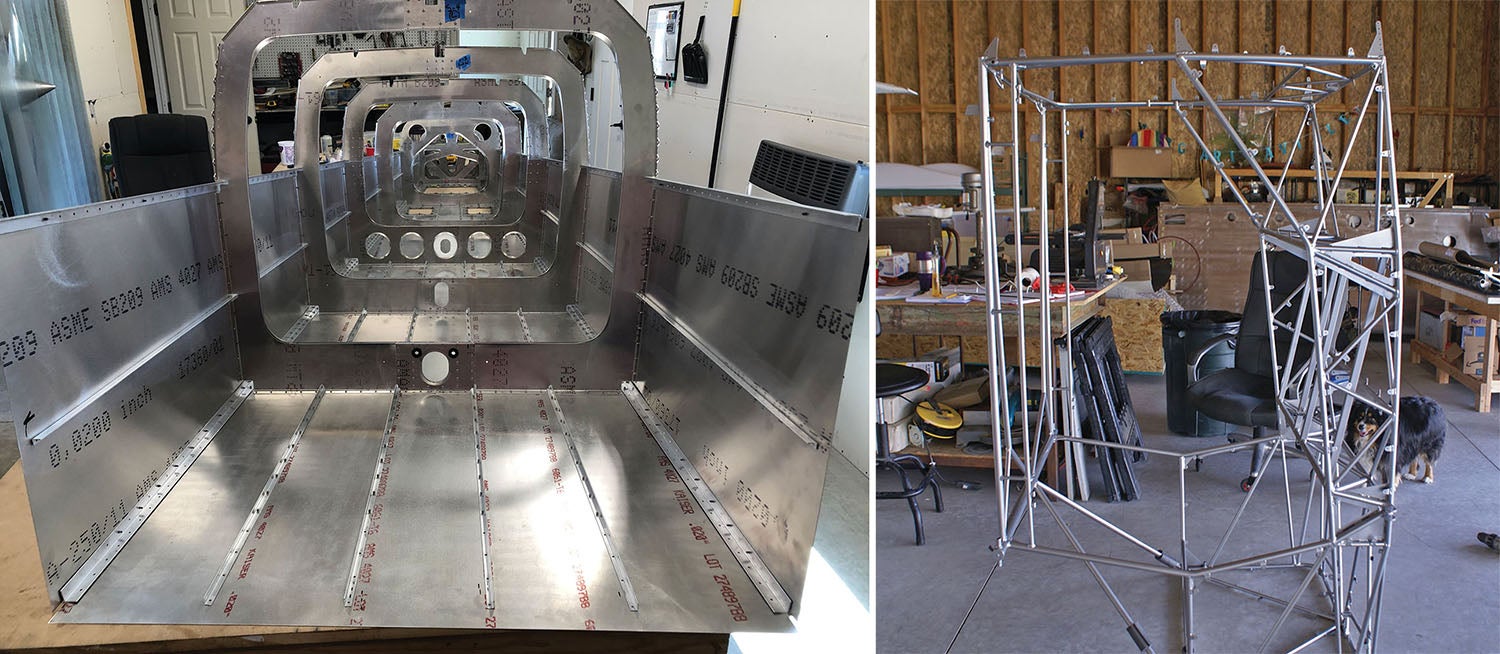
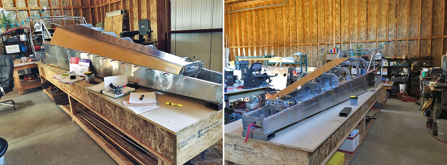
It took us a full day of prepping with locating all the right pieces for the tail cone build and choosing the right place to accommodate it. Here’s the dilemma: The S-21 is more than 22 feet long overall, with much of that between the cage and the tail cone. It was clear that we didn’t have room in the separated shop space for the finished assembly—the tail cone and the fuselage cage together. And then there’s the matter of how to get the bottom skin and the bulkheads started. These pieces wanted to be built upside down on sawhorses, so that suggested we move out into the hangar.
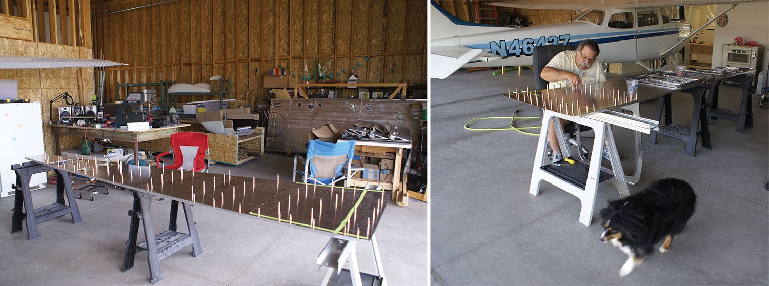
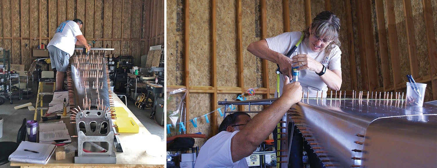
Actually, not so fast. We took advantage of the nice flat workshop table to begin attaching the stringers and longerons (long metal pieces) to the bottom skin. These provide strength to the part and help it maintain shape and could easily be done on the table.
Once that was completed, though, we had to move out to the hangar. That’s because you build the tail cone upside down balanced between sawhorses and attach the bulkheads (rib-like frames inside the tail cone) hanging down from the bottom skin of the tail cone.
Once again, Mike did his magic to make sure each bulkhead was flat, adjusting them with the fluting pliers. It is super critical at this time of the build to make sure everything is straight. You really don’t want to have any twist built into the tail cone! One of the little things I learned was to identify the areas not to rivet and tape them off so I didn’t continue on with riveting in the wrong holes when the time came.
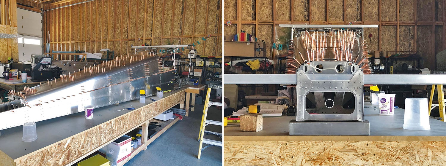
Pretty soon we were able to get all the bulkheads pointed the right direction, then get them all Clecoed and riveted in place. Another helpful thing for me was to label each bulkhead with a station number (per the manual) because the text of the manual frequently refers to the various stations—they are numbered front to rear, so it’s pretty easy to figure out that Station 7 is ahead of Station 8—even upside-down! It was really fun to see the shape of the tail cone starting to appear. There were more stringers and longerons to get into place on the sides of the bulkheads to give the tail cone strength.
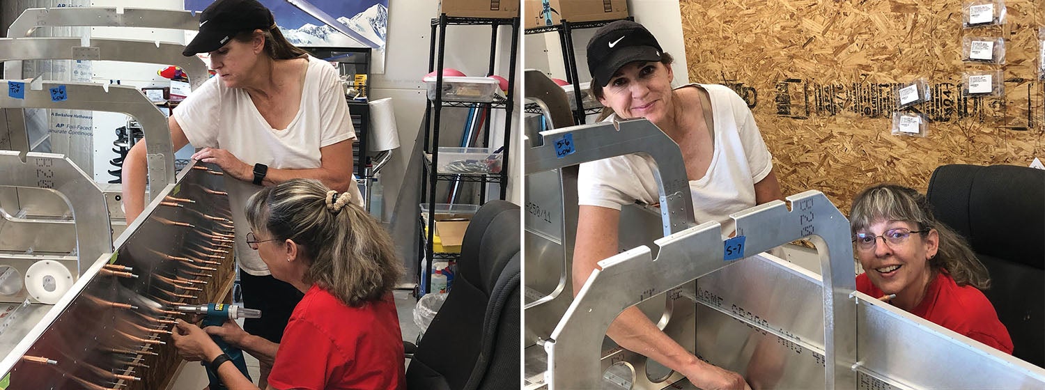
Next logical step was to get the side skins on. We were lucky this day to have our neighbor friend Heather over to assist us. It turned out to be extremely helpful to have another set of hands. While she was here, we were able to get the left side skin Clecoed on, riveted, flipped and carried into the workshop where we attached the right side skin. It was fun having Heather there to assist because even though she is a very experienced pilot, she had no experience building. It was great sharing the build with someone when it’s as basic as, “Here’s how a Cleco works!” This was a great part of the build for her to see, because you could witness huge progress for the day’s work.
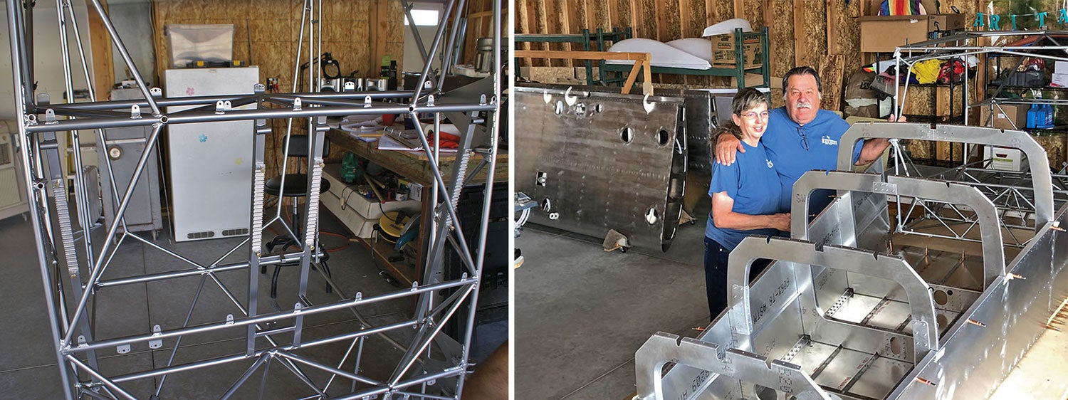
Paul and Louise, next door, assisted us in moving the welded-steel fuselage cage (as provided with the kit) from our storage area by the Cessna. We had already assumed we could not fit the whole assembly into the workshop, but we now confirmed it with several measurements. The only real option was to continue the build in the hangar space. This required tearing down the heavy worktable Mike had constructed and moving it out to the hangar so we would have the surface area and elevation necessary to continue the build. Since I have never been involved with a large project like this, I never realized how flexible you need to be with the space you have! (And, yes, I’m grateful to have as much as we do. Hats off to all you who have built in two-car garages, or less!)
Mike, being the genius he is, had the foresight to realize that this would be a great time to put in the seat rails rather than wait until after the tail cone was attached. They need to be accessed from the bottom of the fuselage for attachment, so why have the awkward tail cone attached and put them on later? Great idea, so we positioned the fuselage cage on its nose, making access easy to the area needed, and got the seat rails on without a problem.
Pieces Come Together
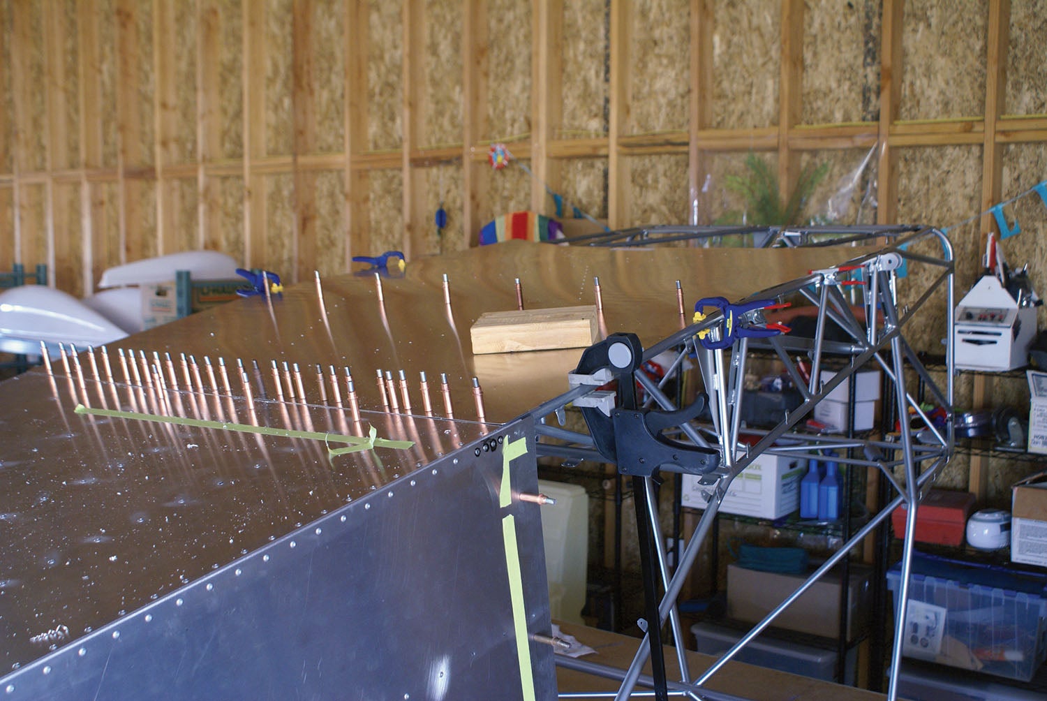
We were finally to the daunting task of mating the tail cone to the cage. We prepped by watching an “Eddie video” on the RANS site so we had a good understanding of how this was supposed to go. Once again, with the assistance of neighbors, we were able to get the fuselage cage up on the table along with the canoe (partially built tail cone) and begin sliding the longerons from the tail cone into the cage at just the right angle. The longerons don’t penetrate into the cage, stopping just at the trailing edge, but the angles still all have to be correct.
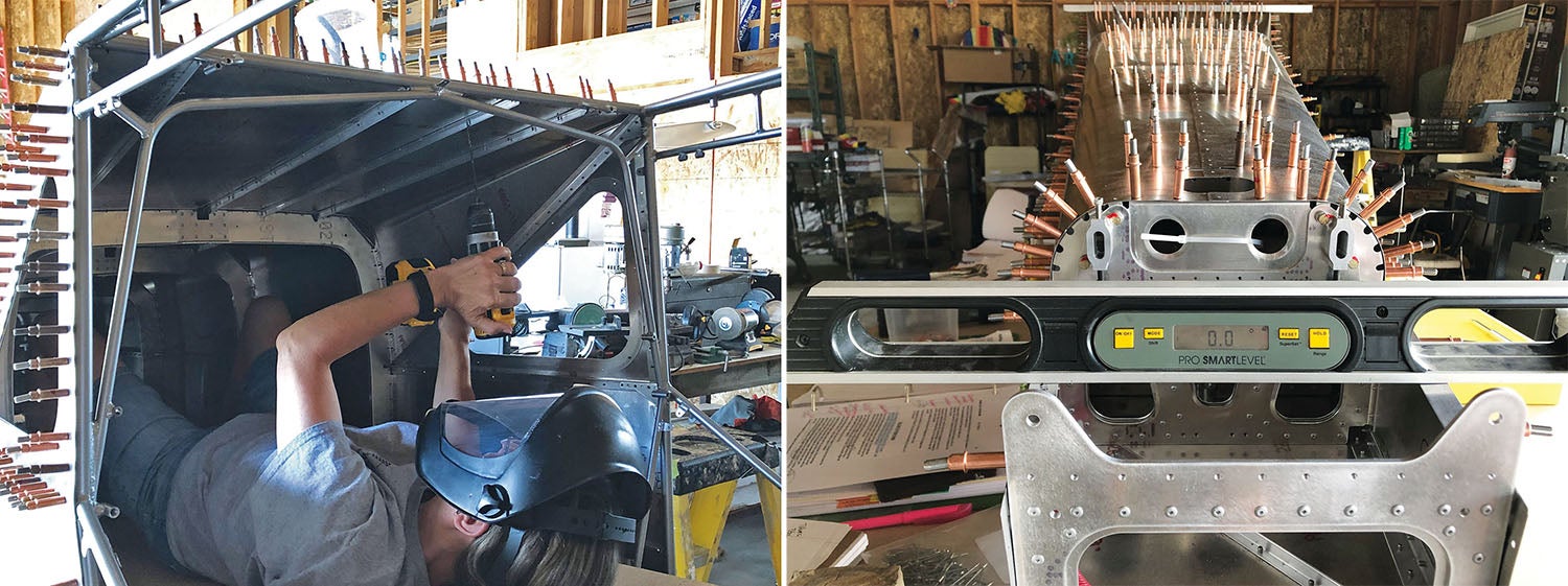
We had to brace the forward part of the fuselage on our steel 2x4s and move them slowly back under the fuselage to get the proper angle between the cage and the tail cone. Because there are so many angles to check in this process, it is challenging to read the manual and make sure that we are interpreting how to correctly measure things. It is extremely important to get this exactly correct. There is not only the angle of the tail relative to the fuselage you need to consider, but you also need to check to make sure there are no twists present. We took our time, tweaked and measured back and forth until, finally, we were to the precise tenth of a degree on our digital level. We transfer-drilled the two middle and two lower longerons to the cage, Clecoed the longerons from the tail cone to the fuselage cage and remeasured. Perfect! Oh my, what a relief. I think it was more nerve wracking than difficult, really.
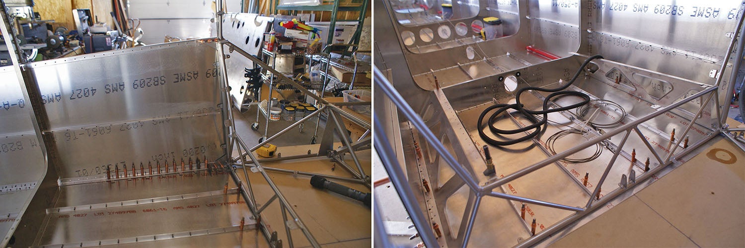
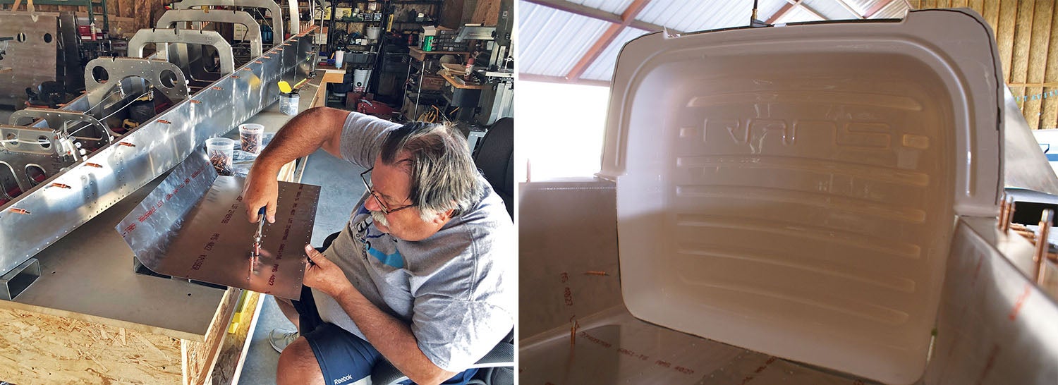
We got the rear baggage area pieces pulled together and properly fitted according to the manual, including the fitting of the S-4 (Station 4) bulkhead close out, which looks like a small bathtub with a RANS imprint on it. It was pretty cool working on this part and being able to visualize what the interior of the plane would look like. Final fitting of the tub would have to wait for the top skins to be in place, so the tub gets set aside at this time.
There is so much work that needs to be done still to the interior of the tail cone to prep for all the inner workings that go in it. Kind of like the wing, there is a lot that goes on here! We had the rudder cables and pulley hardware that we installed, elevator pushrod and a conduit tube for the wiring going the full length of the tail cone for electrical needs later. Before closing out the tail cone, again like the wing, you want to make sure as much of this work is done before putting the top skins on. You really don’t want to have to get back in here if you can avoid it!
Now that all the inner workings of the tail cone were in place, it was time to close out the tail cone with the right and left top skins over the tail cone and the right and left front top tail cone pieces, which are actually on the aft end of the cage locking the cage with the tail cone. The tricky part of this was to not have any pillowing of the skins, so you really need to be mindful when fitting to get the skins just right and to do your transfer drilling in exactly the right places. I got to use the edge forming tool for the first time after practicing a bit on some scrap. It came out pretty nice if I do say so myself! Another tricky part is to get the stringers that extend over the aft part of the cage bent correctly. It is critical when joining up the skins that the measuring for level continues throughout the skin fitting process, because once these skins come together the tail cone shape is locked in.
Final fitting of the S-4 bulkhead close-out (the tub) came after the top skins for the tail cone were fitted, but before the aft cage right and left top tail cone skins were fit—for ease of being able to reach the area we were working in. This part was a bit of a pain because we had to pull the tub in and out of the plane several times to get the cutting and filing of the piece just right to fit the area. In the end it all worked out, and it was set aside for a later date when closing out the tail cone was to really happen—someday in the future!
The only difficulty we had with the fitting of the aft top tail cone skins was that they needed to be drilled from the inside of the cage through the stringers into the top skins. We decided the best way to accomplish this feat was for me to lie on my back inside the tail cone and drill over my head, then have Mike insert Clecoes from the top down. It was a bit of role reversal from our usual routine, but I didn’t mind that. It was nice to know that I was capable of getting into a tight spot and fully capable of doing the drilling myself.
Prickly Fellow!
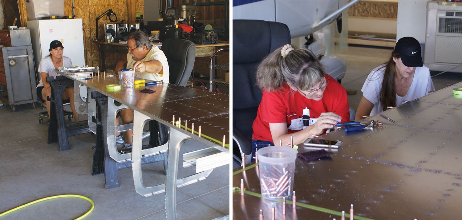
At this point, our little plane looked like a porcupine with all the Clecoes coming out of it. Final alignment check gives us zero twist. Victory is ours! This part of the work is now familiar once again. un-Cleco, deburr and de-sticker all pieces and parts only to Cleco all the skins back together again for “Rosie” to take over. I started riveting the centerline (the spine) of the top tail cone and worked my way down each of the right and left skin side rows toward the bottom to avoid pillowing of the skins, then did the same for the top front tail cone skins working from the center out. There was a lot of balancing on ladders and working from on top of the table with long reaches, but taking every bit a little at a time is the key to getting through it.
There was a new twist on this part of the riveting that I hadn’t encountered before. I had to use stainless steel rivets (which were really big!) in the areas where the aluminum was attached to the steel cage. Mike helped me out by dipping these rivets in paint before dropping them in the hole to rivet to help prevent corrosion later. (Not like there is a lot of moisture here in Nevada, but it’s probably a good idea.) The longerons connecting the tail cone with the cage were riveted and we were finally locked in!
The bottom cage skin was the next skin to attack, but what was the best plan here? We finally decided to invert the structure and work on it upside down. We figured that it would work best this way if gravity was our friend to try to get this skin properly aligned and in place rather than fighting with it over our heads and us underneath it. It actually worked out very nicely this way. I really would not have wanted to be transfer drilling over my head with this large skin! We really had no issues getting the bottom skin drilled, fitted and Clecoed as we went, followed, of course, by un-Clecoed, deburred and riveted. The routine was well rehearsed and came together nicely. You’ve probably heard other builders recall times when this kind of repetition becomes a comfort, things you know how to do and are getting better at all the time.
With the assistance of neighbors once again, the plane was flipped right side up and all was back to normal. Next on the “to do” list were the two side skins to be fitted for each side of the cage. These were a little bit of a pain just to get them cut and filed in the right places to get them to lie right. That was really the only unique part of dealing with the side panels, which are actually more cosmetic (and aerodynamic) than structural.
Even though this is the Reader’s Digest version of this portion of the build, I’m sure you understand it doesn’t happen overnight. It is a lot of work with long hours. This portion of the build took us about five weeks to accomplish with both of us working 4- to 6-hour days, with only a few days off. It is work, but it is so satisfying to see the results and see the progress made. (As a side note, we’ll be taking the next issue off to get caught up with the build but will return in the January magazine.) I am truly enjoying seeing our little plane coming together. I am so looking forward to the day when she will fly!


