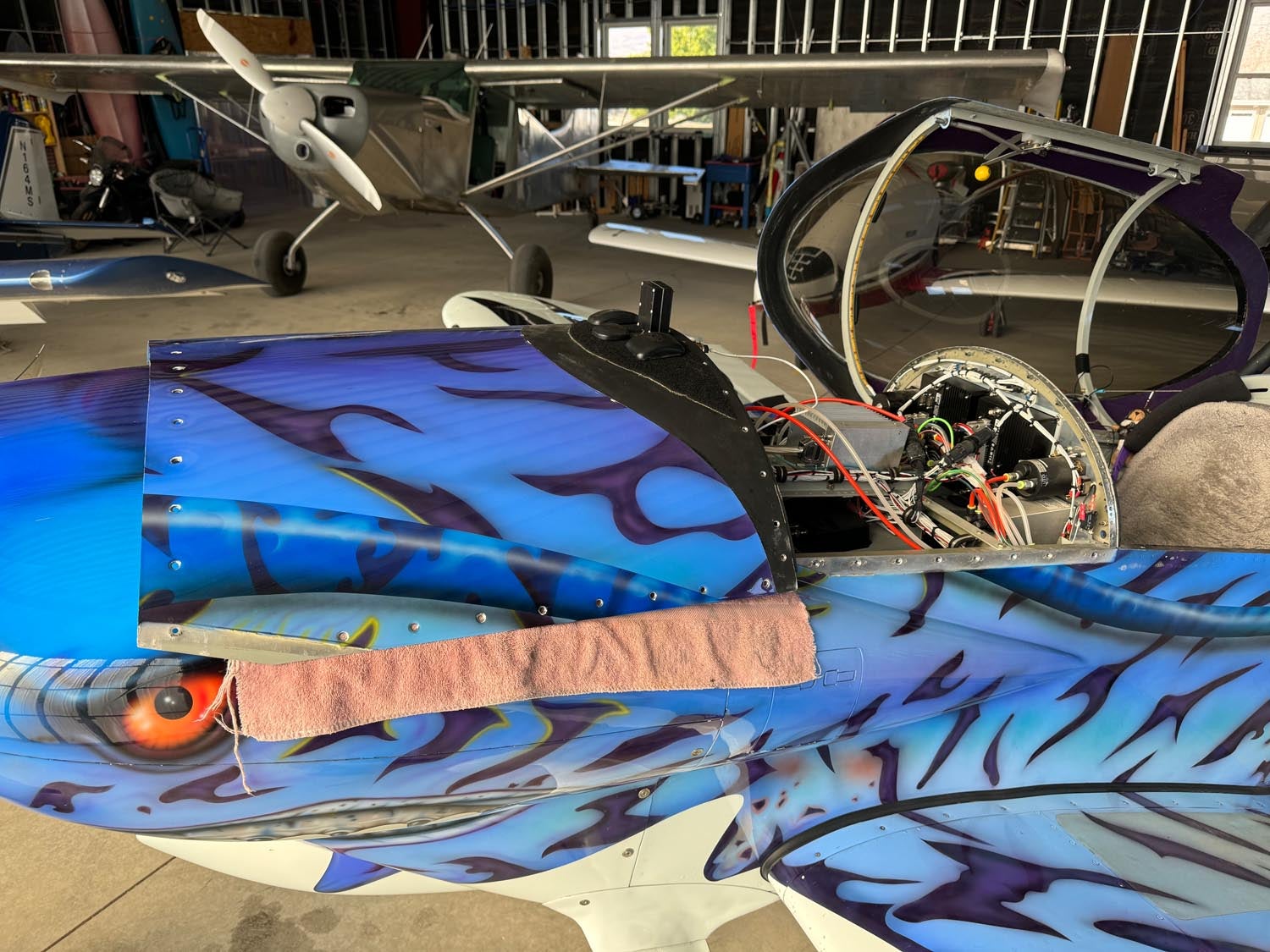
In my ongoing effort to equip our home fleet of airplanes with as many Angle of Attack systems as possible, we recently upgraded the G3X Touch in our RV-3 to provide AoA visuals and tones (along with the existing AOA Pro from Advanced Flight Systems). The AoA Pro has always had two calibrations – one for flaps up, and one for flaps down, with the flap position provided by a microswitch that goes to ground when the flaps deploy. In reality, it is a “flaps not up” switch, but in practice we always use full flaps when we deploy flaps, so operationally it is unambiguous. During initial installation and calibration of the G3X AoA, we did not have flap position going to the Garmin equipment, so we had only a single calibration curve for “flaps up”. Yesterday, we remedied this with a little minor surgery.

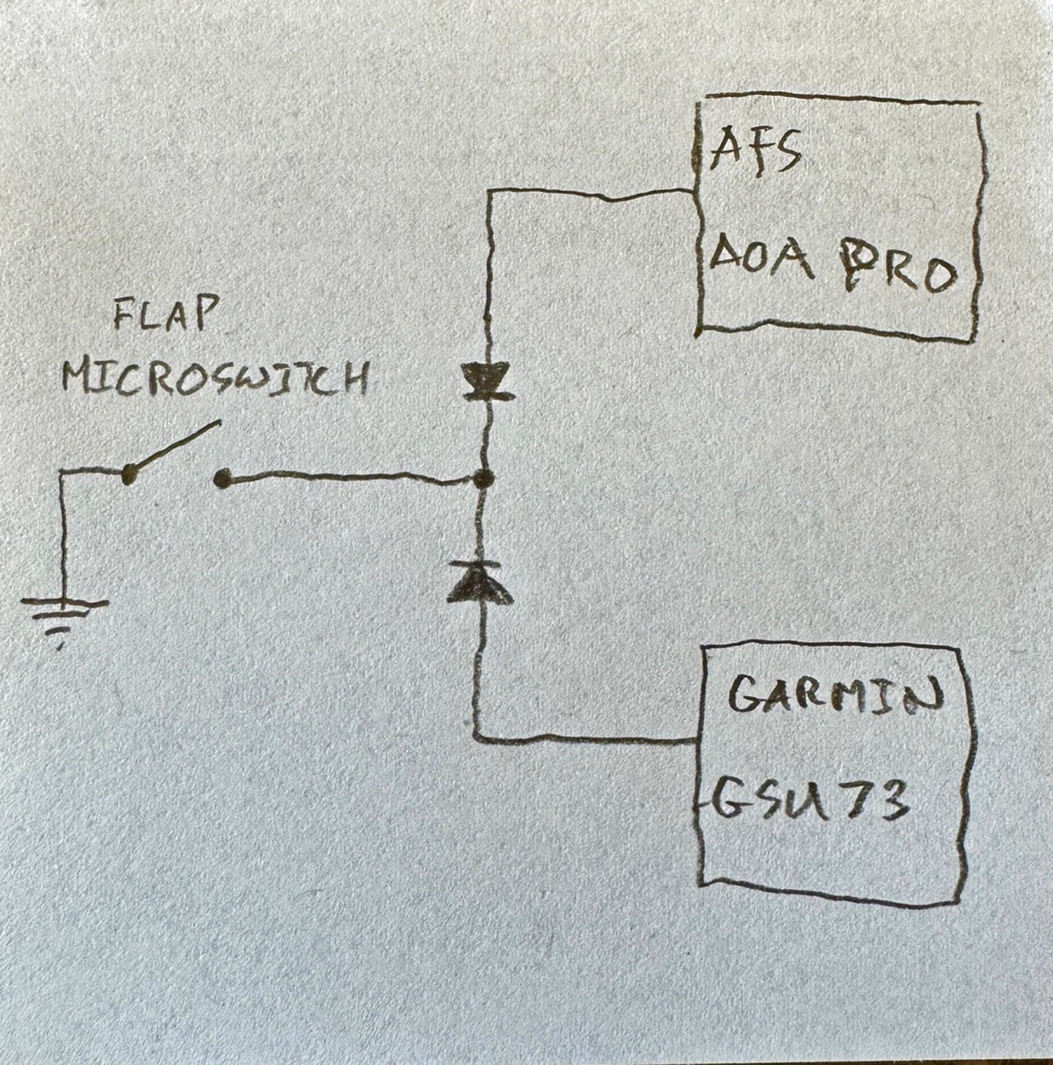 Both the AOA Pro and the G3X were happy to see a “ground” when the flaps were deployed, but I didn’t want to add a second switch for the new system, as it would require additional wiring from a difficult spot behind the pilot seat to the panel. Sharing a single wire directly to the two systems could conceivably create some weird electrical issues if the two boxes didn’t like being tied directly to a common ground, so I decided a little diode isolation was the safest way to go. Diodes act as one-way valves to the electrons so that current can from either box to ground – but not between the two boxes. Making a diode pack involved soldering together a couple of ubiquitous 1N4001 diodes (a pack of 100 costs about six bucks on Amazon), with their cathodes joined and pointing to the switch, and the anodes separate and going to the two boxes. Built up (with heat shrink covering), it looks like this:
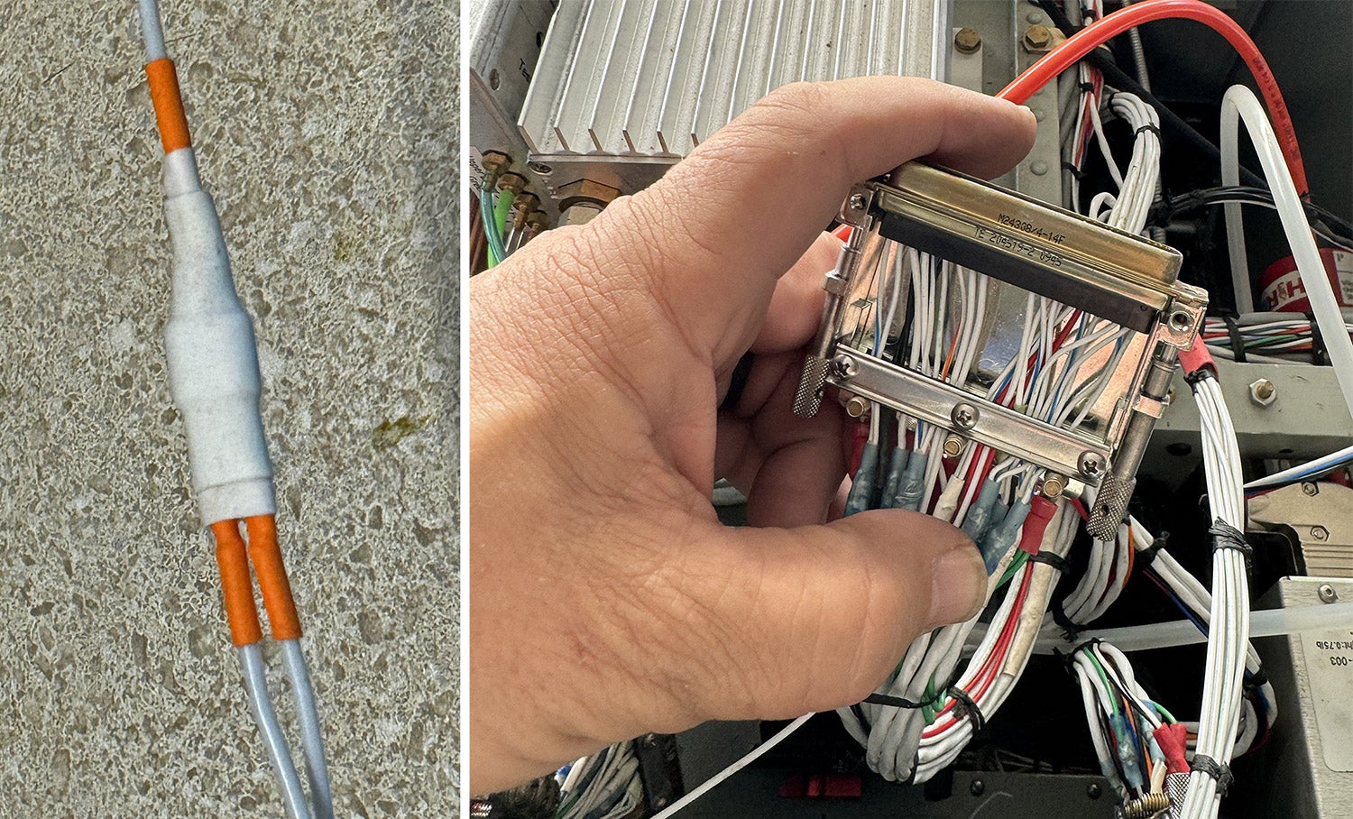
Since the wire from the flap switch was already up under the instrument panel to serve the AOA Pro, all I had to do was remove the deck (skin between the top cowl and instrument panel) to access the area to be rewired. We built our RV-3 with screws specifically so that we could access the avionics easily. Bundle everything back up neatly with lacing cord, replace the deck, and turn on the power to the EFIS, with eh EFIS booted into CONFIG mode. Once there, you tell the EFIS that discrete 1 is now the “flaps down” signal, and the AoA calibration screen will now magically show you a flaps down calibration option. It was a nice afternoon with no wind, so we launched, climbed to altitude, performed the calibration for flaps down, and landed, all in 12 minutes.
![[Credit: Radiant Technology]](https://www.kitplanes.com/wp-content/uploads/2026/04/550095_5165745cc27748a598699799d796fd94mv2.jpg?w=218&h=150&crop=1 "Radiant Technology Unveils SafeGyro")


Diode isolation between the two boxes is a good idea, but I would use a Schottky diode, such as a 1N5819 ($0.40 each from Mouser and DigiKey at quantity one). The Schottky diode has less voltage drop, to make it somewhat more certain that both boxes will see a logic low when the switch is closed. And my reason for thinking it’s a good idea is that the two boxes might pull the input up to different voltages, e.g. 3.3V on one box and 5V on the other. I’d be less concerned about tying the inputs of the two boxes to a common ground on a logic input signal.
Not only are the screws on the shield grounds too long, fusion tape should normally be placed around the strands on the strain relief.
Comments are closed.