An arcane bit of wisdom for the joining of wires has been handed down for generations; it is an axiom readily believed and enthusiastically propagated: Make it mechanically secure, then solder for electrical integrity.
This is the first of three articles that will explore the art and science of terminating wires. Mechanical installation techniques call for tools tailored to the wire/terminal combination and the manner in which the terminal grips the wire.
Solder is a time-honored process for both the structural joining of components and crafting electrical connections. This article studies the art and science for the conduct of electrons to and from ends of wires without the use of solder. We’ll consider three classes of terminal wire grips: (1) the closed-barrel grip (both insulated and uninsulated), (2) the closed-barrel, machined connector pin, and (3) the open-barrel, sheet-metal pin.
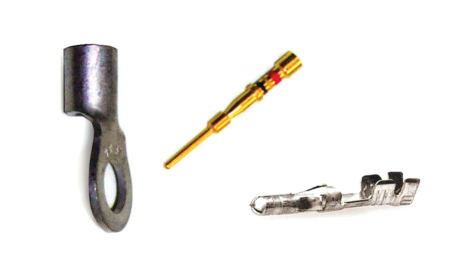
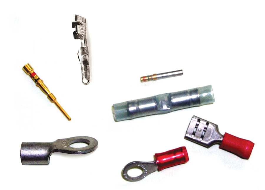
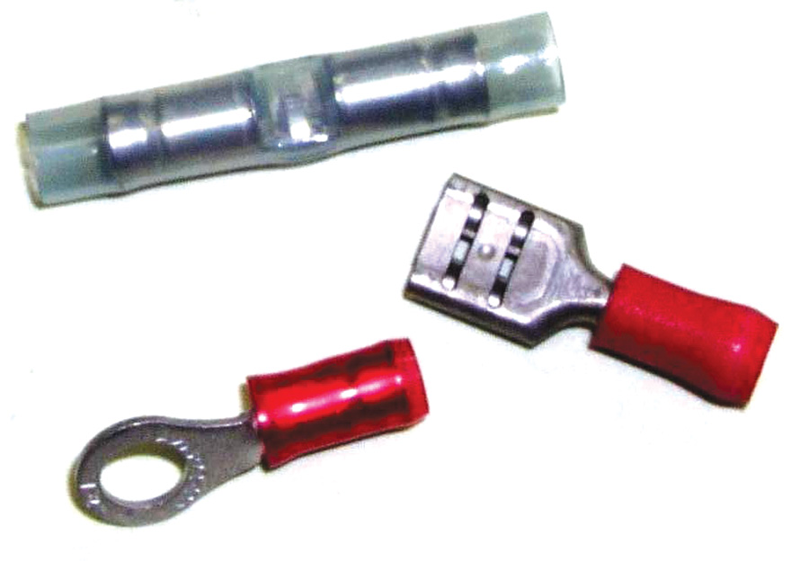
Figure 1 shows a small collection of crimped terminations. Each style is applied with a tool that places the proper crush on the terminal’s wire grip. The goal is to close the voids inside the crimp zone, forming a gas-tight connection between terminal and wire strands. For all practical purposes, the properly installed terminal and wire will become a single piece of metal.
A sampling of what must be trillions of connections in modern electro-whizzies will not produce a single example where solder and crimping technologies are used in tandem. A review of simple ideas for making robust connection to wires argues convincingly against that old axiom. Clearly, the use of solder for joining wires has taken a back seat to mechanically-installed connections (crimping). However, don’t think that solder has gone down for the count. Solder is still an effective process for joining two metals. In some instances it’s the preferred process.
Design goals are the same for all connections to a wire, irrespective of the termination process: (1) establish intimate metal-to-metal contact between wire and terminal for the conduct of electrons, (2) provide protection from the deleterious effects of moisture in a corrosive atmosphere and (3) support of the wire for resistance to vibration at stress risers associated with immobilizing the wire’s strands.
The insulated terminals illustrated in Figure 2 are legacy pre-insulated Diamond Grip (PIDG) terminals. PIDG is a trademark of Tyco-AMP. But just as popular vernacular once referred to all copiers as Xerox machines, so too has the term PIDG come to identify the family of interchangeable devices produced to a common specification. The PIDG style of wire joining calls for two crimps, one that forms the terminal’s wire grip barrel down on the stranding, and a second to form the wire’s vibration support feature down over the insulation.
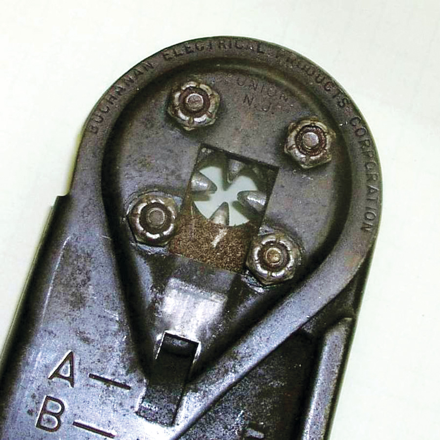
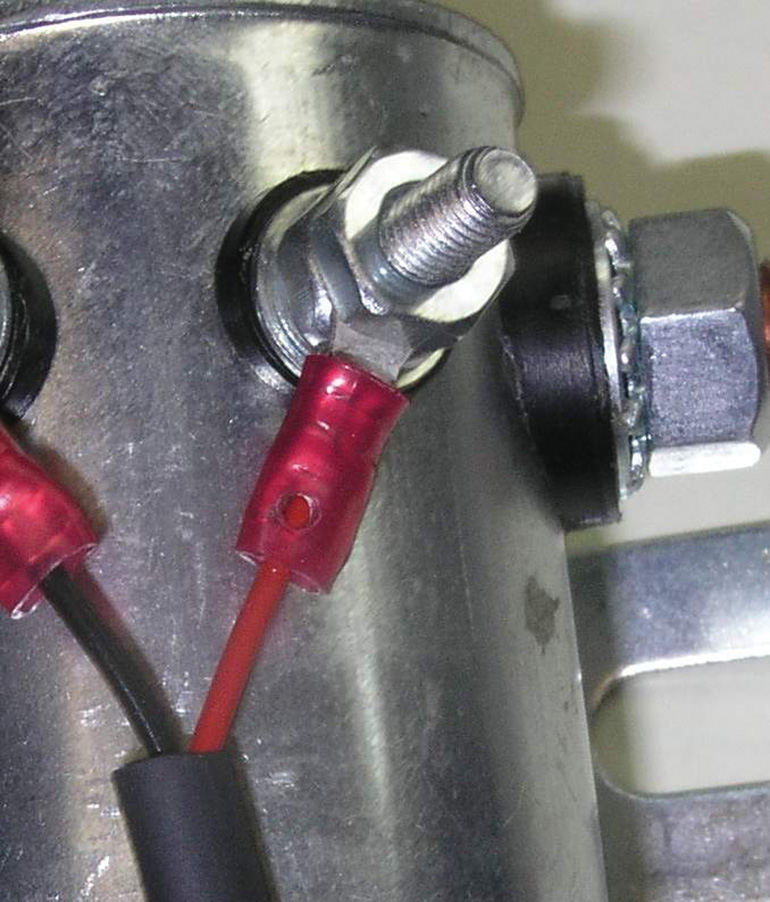
In Figure 3, a ring-terminal is indicated for connecting a wire to a threaded stud. The PIDG terminal here was installed using a ratchet-handled tool (Fig. 4) that brings shaped dies together to deform the terminal into intimate contact with the wire strands.
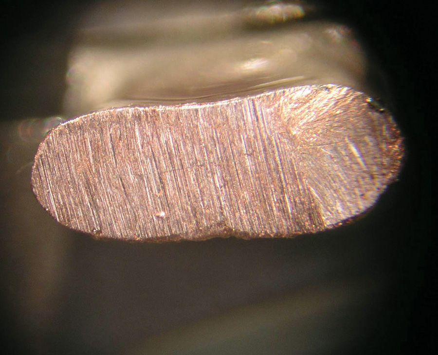
An examination of the wire grip cross section will show that a properly joined terminal and wire have become a single piece of metal (Fig. 5).
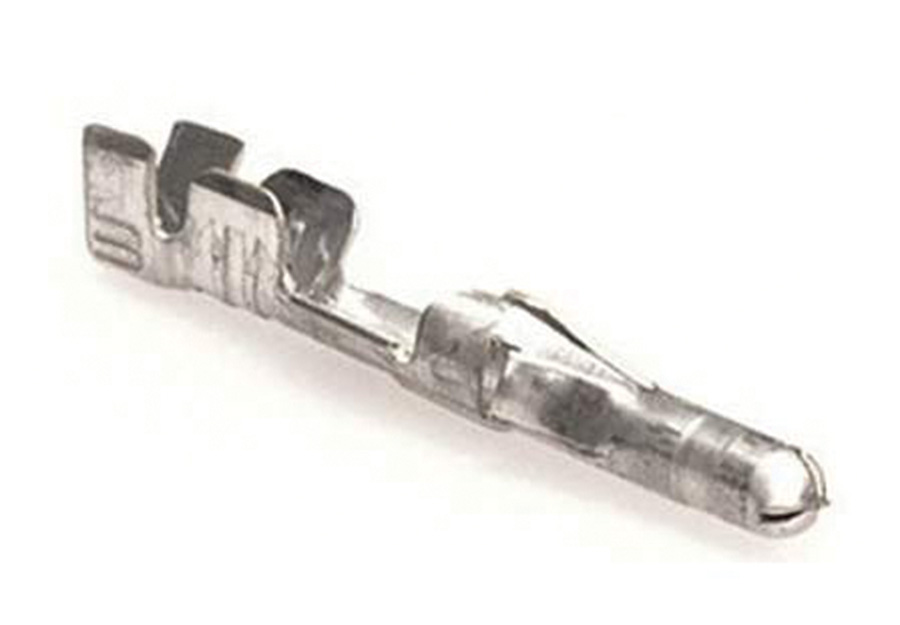
Two classes of uninsulated terminals are illustrated in Figure 6. Both the ring terminal and the machined connector pin are closed barrel. The third connector pin illustrates the open barrel, formed sheet metal pin common to rectangular plastic connectors.
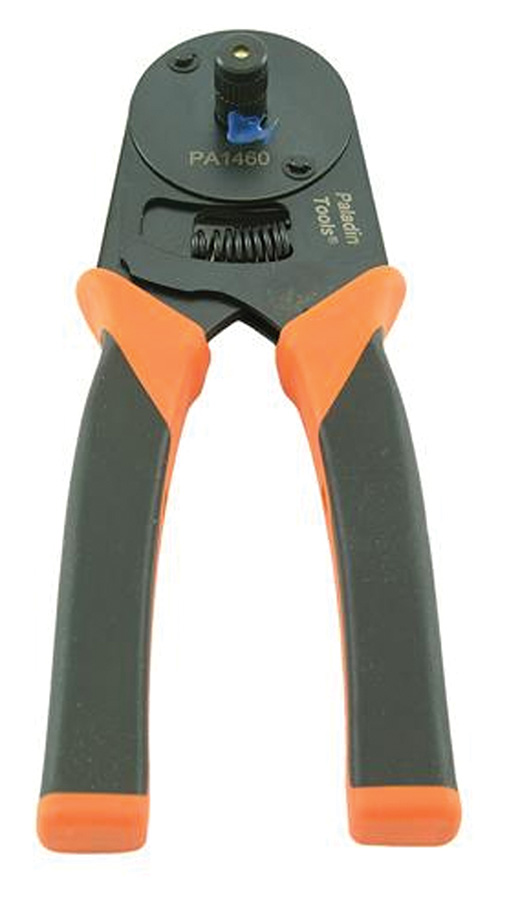
Machined pins and some uninsulated terminals are best installed with a tool that drives punches in from four directions around the wire grip barrel. Figure 7 shows one of several tools suited to the task. The identification and discussion of these alternatives will be detailed in a future article.
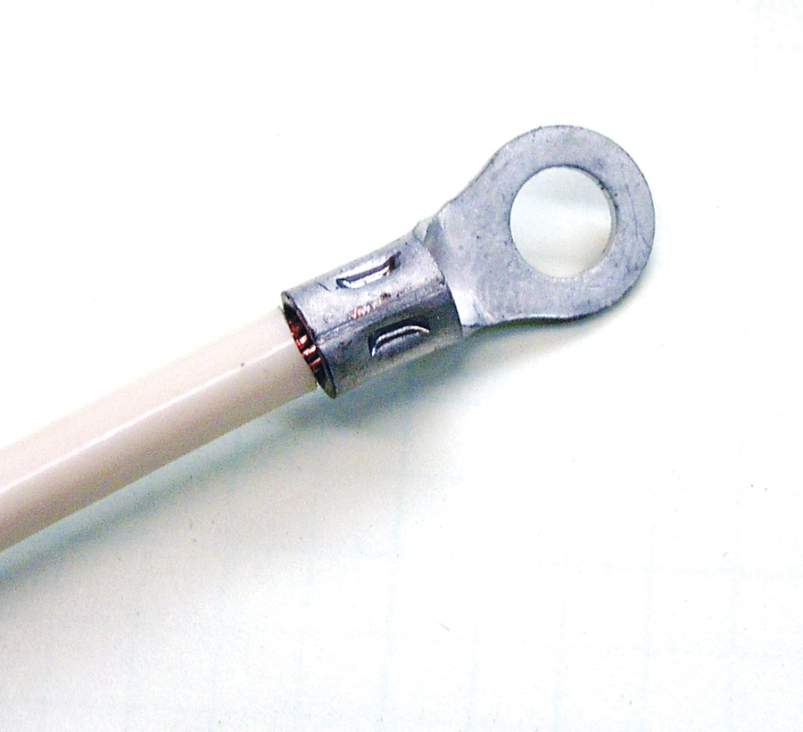
The 4-quadrant indent tool compresses the inside diameter of the wire grip into intimate contact with the wire strands, without deforming the diameter of the outside envelope. Two of the four indentions are visible on this uninsulated ring terminal installed on a 6AWG wire (Fig. 8).
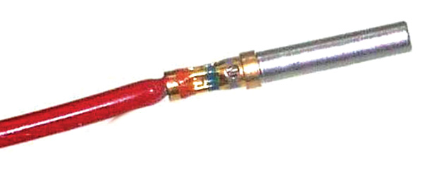
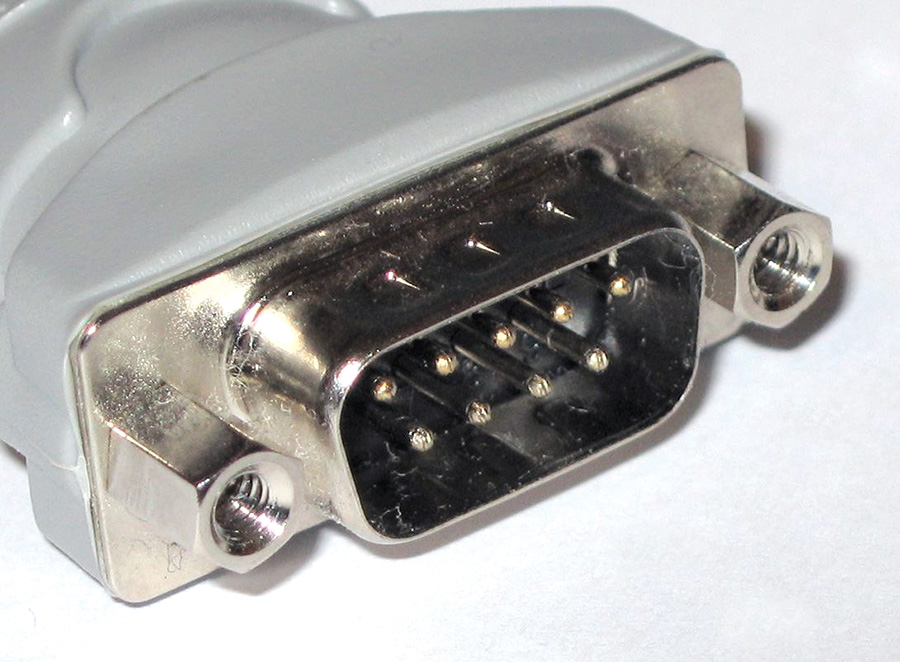
A smaller 4-quadrant indent tool (Fig. 9) installs closed barrel, machined crimp-on pins (Fig. 10), typical of those found in D-sub connectors (Fig. 11).
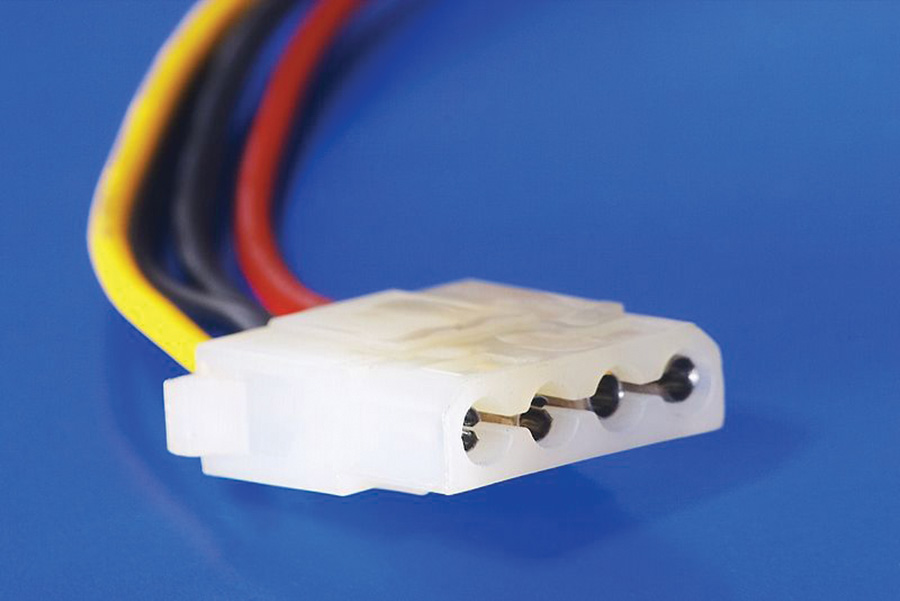
The open barrel, sheet metal pin (Fig. 12) requires some special attention for installation tools. This pin is typical of those found in Molex and AMP rectangular plastic connectors (Fig. 13).
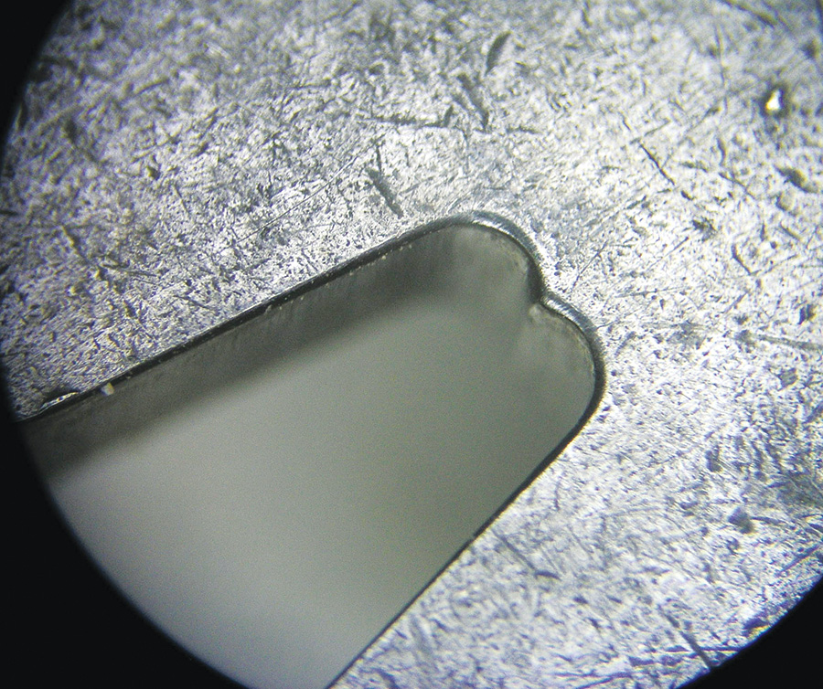
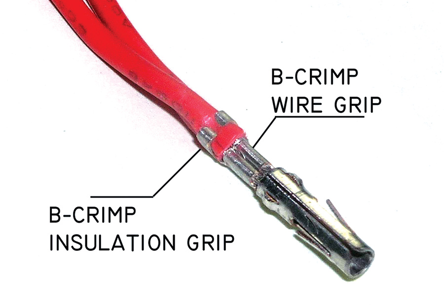
Figure 14 is a close-up view of the B-crimp die. The sculpturing forces wire-grip tabs on both sides of the pin to execute U-turns, reversing course and diving into the strands of wire.
This tool forms the characteristic B- crimp profile (Fig. 15). B-crimp terminations
predominate in production of consumer goods. They found their way into Cessna single-engine airplanes in the late 1960s, when AMP, Inc. sold Cessna on the philosophy of breaking ship’s harnesses into segments joined by plastic Mate-n-Lok connectors. The history of these connectors in light aircraft has been good.
The take-away for this article is the requirement for crafting a gas-tight joint between terminal and wire. This is achieved by application of sufficient constrained force necessary to deform the terminal’s wire grip into contact with strands of copper. Figure 16 is a cross section of an installed open barrel B-crimp terminal, showing adequate crush.
Mechanical robustness and gas tightness are synonymous conditions. If you have achieved either one of these conditions, the other naturally follows. This pairing of conditions offers the prevailing argument for discounting the ol’ electrician’s axiom. If a terminal is properly crimped onto a wire, what value is to be gained by adding solder to the connection? The answer is none.
The retort might be, how do you know that the wire is properly crimped? Adding solder is cheap insurance against a crimp of unknown quality. Uncertainty is the partner of ignorance. The goal of this series is to offer some understanding of how all these ingredients feed into a recipe for success in the crafting of your airplane. Understanding the fertilizer offers confidence that solder is completely unnecessary for most—if not all—terminals installed on wires in your airplane.
In the next installment we will explore the nature of solder as a joining process. We’ll also discuss the modern philosophies and processes for the use of solder.


