 I’ve always had a gear-driven alternator on the accessory case, but I recently added a belt-driven alternator. After relocating my RV-4 to a tower-controlled airport, I needed an alternator that could charge the battery while idling.
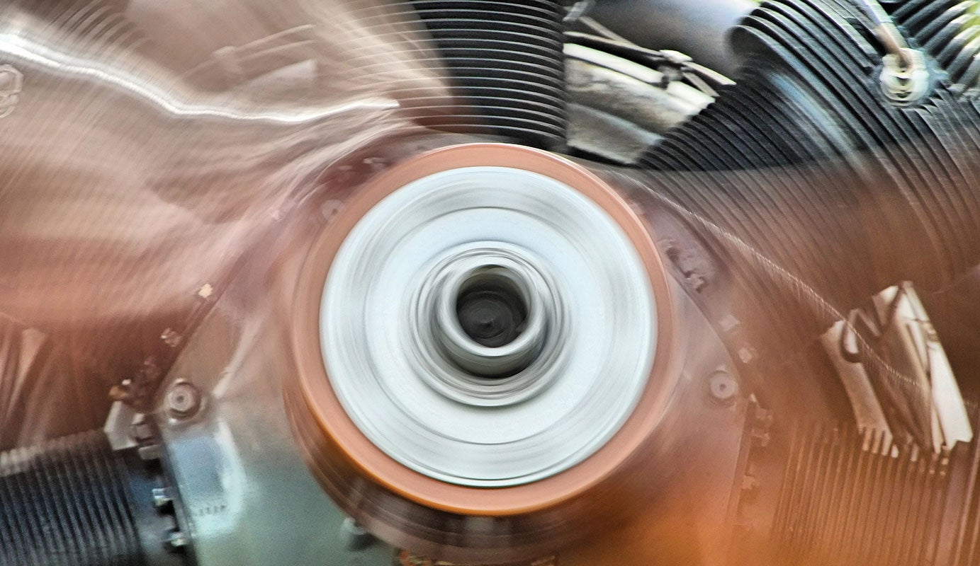
After installing the new alternator and having the propeller off the plane, I needed to rebalance the entire new assembly. I’ve always balanced my prop when it’s been off the plane or after being worked on or inspected. I would just pick the rpm and balance it following the instructions in the balancer’s manual. It usually took about three or four ground runs. However, like many of you, I never checked it at other rpm. I thought if it was balanced at 2400 rpm, it was good to go at all rpm.
Well, that’s just not so, and it’s why the balance manuals say to balance the prop at the rpm you run most of the time. So, why wasn’t it balanced at other rpm? Let’s take a deeper look at balancing and find out.
Why Balance?
Any severe out-of-balance condition will cause vibration leading to increased wear, fatigue of aircraft parts and occupant discomfort. There are three types of imbalances.
- Static imbalance is caused by one side of the propeller assembly being heavier than the other, which is everything in front of the crankshaft flange.
- Aerodynamic imbalance is caused by the difference in thrust of the different blades on the propeller.
- Coupling imbalance is caused by the combining of other rotating mass axes.
Static imbalance is when the center of mass isn’t concentric with the rotating center. In this case the phase angle is in one spot.
Aerodynamic imbalance is caused by one blade producing more thrust than another. The result is a kind of rotating wobble that might be due to different airfoils (repairs) or pitch variations between the blades on the prop. In this case, vibrational magnitude (measured in inches per second [IPS]) and phase angle change with rpm and prop load.
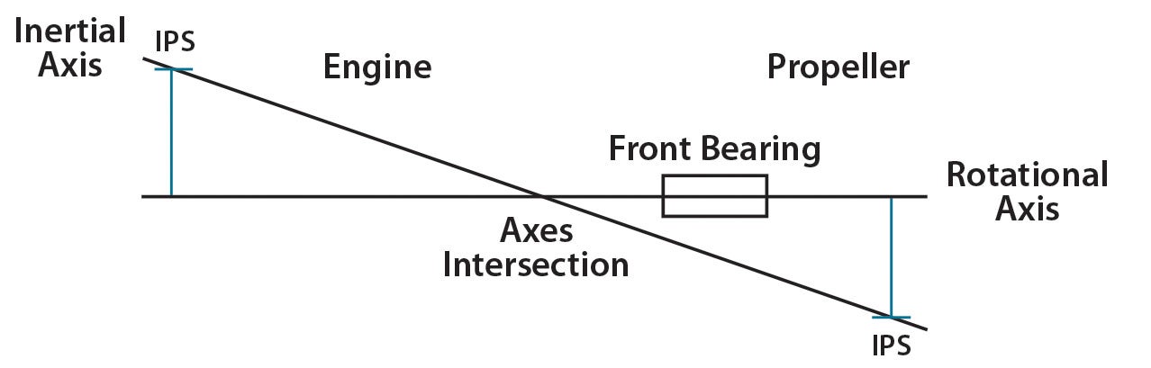
Coupling imbalance is when the rotational axis mass ahead of the front engine bearing is displaced from the inertial axis of the engine, which is behind the front engine bearing. These two axes intersect at the center of gravity along the crankshaft, but they are not parallel and concentric. In this case the phase angles in the front and back of the engine are 180° apart, but the IPS are the same, even though the rotating mass is dynamically balanced.
Coupling imbalance is the most difficult to understand and illustrate. It’s kind of a mass imbalance and an aerodynamic imbalance at the same time, but displaced along the rotational axis so they aren’t in the same plane.
As an aside, this is why some aircraft with certain engine/propeller combinations have rpm restrictions even though the engine/prop combination is balanced! It can be dangerous to operate continuously at coupling rpm ranges.
Then, to complicate things further, the propeller imbalance is composed of all of the mass imbalance, aerodynamic imbalances, and possibly a bit of coupling imbalances as well. And of these imbalances, the mass balance—if it is perfect—remains balanced at all rpm and the phase angle stays in the same location if the mass balance solution is in a single plane.
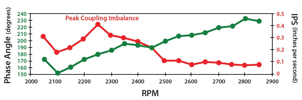
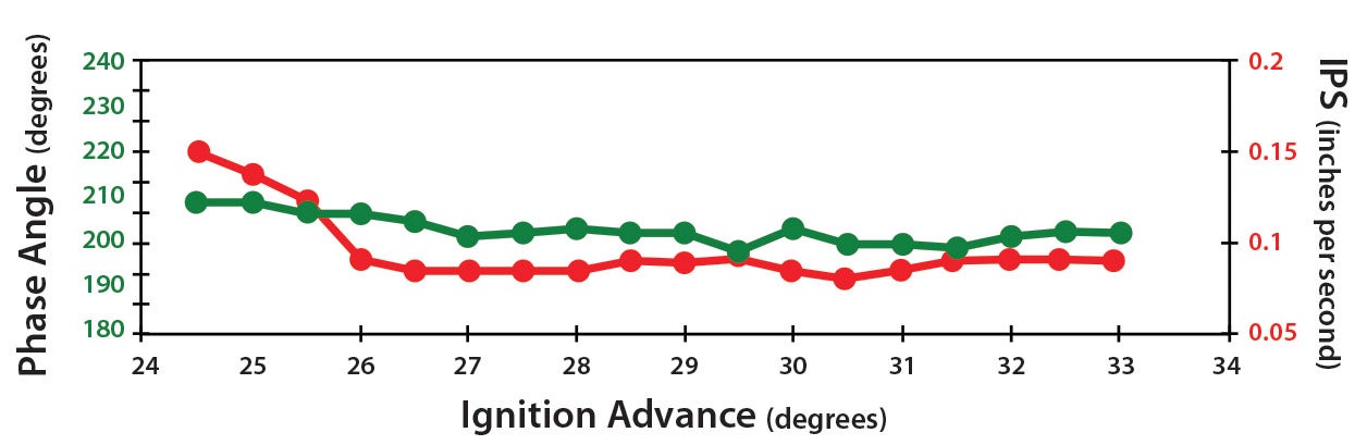
For dynamic imbalances, the IPS changes with the phase angle as load and rpm changes. Then you may also be running at the edges of the coupling imbalance range at times as well. (See the typical imbalance graph for rpm on Page 28. Every graph may/will vary with each plane’s individual propulsion system). It’s interesting to note that advancing the ignition timing decreased the IPS for the first 1.5° of advance, then had no effect at all on the remaining 7° of advance as the MAP decreased with increasing altitude, and there was essentially no effect on phase angle.
Balancers
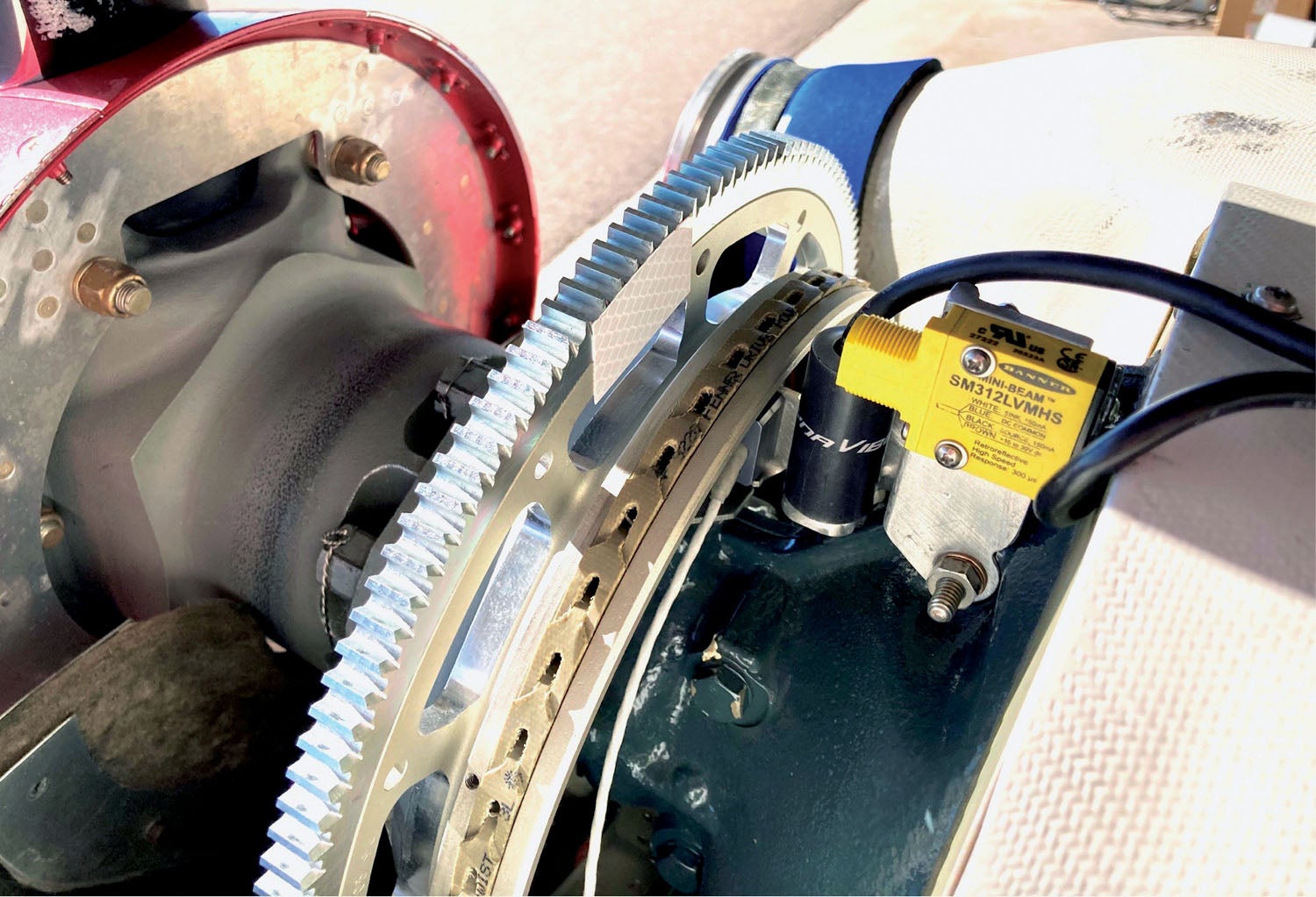
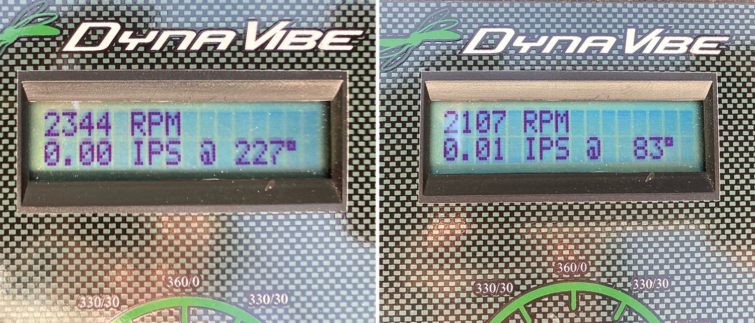
There are a few on the market, with prices varying depending on available features. Of course, the more they do, the more they cost. One of the more popular models, and the one I use, is the DynaVibe Classic, which will do everything you need, costs less than many others and is simple to operate. The system uses a photo tachometer to provide rpm and location information via the light reflected from the reflective tape that goes on the back of the prop blade or flywheel. An accelerometer provides acceleration magnitude information to a handheld computer that produces a readout of rpm, IPS and phase angle on a screen.
All of the balancers available do essentially the same thing. They have the same or similar sensor accuracy, and all can produce acceptable results. Note that after balancing, even a few bugs can throw the balance off a little. If the bugs are asymmetric on the prop, they can cause mass and aerodynamic imbalances.
The difference in balancer cost doesn’t have as much to do with how accurate the balance ends up, but more with how much you want the balancer to do for you. The more complex units can diagnose engine problems, for example the magnitude of the coupling imbalance (with multiple sensors and locations on the engine). They can give you detailed information regarding the amount of corrective weight and its location, and divide that information into adjacent bolt locations on a starter ring. Some units also record the balance results for you. Just follow the manufacturer’s instructions, and you can end up with the results you want.
These balancers can be used on the ground or in flight, but the physical setup is the same idea. The mounts must be stiff, with the accelerometer as forward and as near the centerline of the engine case as possible, and the photo tachometer should be positioned perpendicularly to the back of the prop blade or flywheel. In-flight balancing, if you can do it, is very good on a smooth day and provides really reproducible data.
How to Balance Properly
The best advice is to follow the balancer’s manual! Balancing procedures aren’t difficult and can actually be fun.
Inspect the plane for things that can have an effect on the balance result. Needless to say, anything that holds the engine to the plane, is a rotating part on the engine, or is part of what is spinning must be in good condition; otherwise they can produce poor balancing results. Even an imbalanced alternator can produce vibrations.
The engine should be in good condition. If it is running rough, your results may be suboptimal.

The prop blades must track within acceptable limits. Just remove one set of spark plugs and use a dial indicator. The recommended limit is +/- 0.0625 inch. Mine is currently +/- 0.011 inch, which may be about average.
Test conditions have to be good with little wind or gusts. The balance manuals will define the test conditions for good balancing.
Be aware that certain aircraft will have an inherent disadvantage for ground-run balancing. For example, depending on the number of blades on the propeller, a taildragger with short landing gear will have two or three pulses per revolution that will input a vibration variable into the airframe every time the blade goes by the ground. This may, or may not, be a potential problem.
Pick a defined rpm (the one you run most of the time) and repeat the same rpm for sequential runs; do not let the rpm vary.
Correcting an Imbalance
There are only two things you have to find out to correct an imbalance at a specific rpm:
- Acceleration magnitude, measured in inches per second (IPS).
- Location, measured in degrees (phase angle).
Locate the position by phase angle, then add to the light spot or subtract from the heavy spot by adding or subtracting weights on the flywheel or spinner plate that equals the IPS. The balancer you use will have an easy formula to determine the amount of weight, and from the phase angle you can determine the location to add or subtract it. Just follow good techniques and proper procedures in the manual. It’s easy.
Here are other things that can affect balance and why you don’t want to vary them during the procedure.
- Gyroscopic precession causes the phase angle to shift into the direction of rotation of the propeller as the blade load increases. This is the principle that exists when a force is applied to a spinning object. It rotates into the direction of the object’s rotation and then reacts. So as the asymmetrical blade load increases, both the phase angle and IPS change.
- Changing rpm changes the centrifugal forces (IPS).
- Changing manifold pressure (MAP) changes the thrust loading on the blades. If they are uneven, it increases aerodynamic imbalance.
IPS
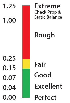
The lower the IPS (the acceleration magnitude of the imbalance in inches per second), the better for a good balance result. It is unlikely that you will notice much difference in the results between 0.07 IPS and 0.00 IPS. However, your airframe may notice over time with things like baffling cracking or rivets loosening. When getting a commercial balance, many providers will stop at around 0.10 IPS. As you get closer to 0.00, the phase angle can begin to be a variable, making it more difficult to put the weights in the proper location. And as you get closer to 0.00 IPS, the weight of the lightest bolt and nut may be too heavy for that location. Paul Dye had a very simple way to solve this problem by lightening the bolt and then adding titanium and aluminum bolts as alternatives (see “Hollow Bolts for Propeller Balancing“).
As you do consecutive runs, an IPS variability of around +/- 0.03 inch is essentially the same reading. If you’re doing in-flight data collection, you can easily take many consecutive readings, throw out the two extreme outliers, average the rest and you’ll get very good data.
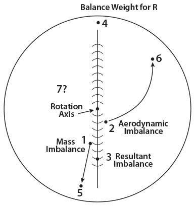
The IPS and phase angle can change as the rpm changes, and that’s why you balance at the rpm you use most of the time. The weight (R) at Position 4 in the graph above is the resultant weight that compensates for Position 1 and Position 2 imbalances at a specific rpm. If you observe the IPS and phase angles changing in value with changing rpm or MAP, you may be getting coupling and/or aerodynamic imbalance imposed on top of a rotating mass balance. The imbalances aren’t in the same spot in the rotating plane. The mass imbalance (1 in the diagram above) is in one spot (a single phase angle) relative to the central rotation axis and will only change IPS with increasing rpm. However, the aerodynamic imbalance (2 in the diagram) can change phase angle and IPS with increasing rpm as a result of increased MAP or pitch causing Position 2 to change toward Position 6 as prop load increases. So at the increased rpm it would require a totally new resultant solution for Position 7, wherever that may be. Balancing at all rpm is unlikely.
Aerodynamic imbalances are variable and can occur by just increasing MAP at the same rpm. In that case the mass imbalance (Position 1) wouldn’t increase, but the weight (4) to balance the R (resultant forces) would no longer be correct (7). Then throw in coupling, which is relative to the displacement of the rotational mass axis in respect to the engine’s inertial axis, and it can become complicated. If this is how complicated it is for constant-speed propellers, just think about how difficult it is to make a handmade propeller perfect.
If you are using a simple, inexpensive balancer, after a few runs you may end up with weights in a few locations instead of changing the weights and position each time you make a run. That’s OK, but if you want to reduce the location of weights on the flywheel or spinner to the minimum number, you could solve for the resultant (R) of several rotating masses in the same plane. Below is the space diagram for the analytical method.
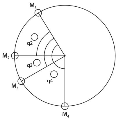
This was my plane after several in-flight runs as I was trying to find a good all-around balance resolution. I was testing at many different rpm that I like to use until I found an acceptable compromise for normal operations. The result was better than fair but not perfect. I also found an rpm range that I am not going to run anymore even though I have a counterweighted crank. The diagram below shows the solution for bolt locations on the Lycoming flywheel. Here is the math:
m = bolt weight in grams
r = radius of the flywheel bolt holes (5.375 inch on a Lycoming flywheel)
moment = m x r
q = angle in degrees from the reference, which is the first bolt position
R = resultant
H = horizontal component
V = vertical component
| Weights (grams) | Angles (degrees from reference) | ||
|---|---|---|---|
| m1 | 8.8 | q1 | 0 (reference) |
| m2 | 15.3 | q2 | 60 |
| m3 | 12.3 | q3 | 90 |
| m4 | 23.4 | q4 | 150 |
Then solve for the horizontal component (moment arm) H.
H = moment1 x Cos q1 + moment2 x Cos q2 + moment3 x Cos q3 + moment4 x Cosq4
Right here, some of you are going, “What the heck…trigonometry?” But this is nothing. Just look up on your computer, “What is the cosine of 0,” and a calculator will pop up and solve things for you. What each component of the formula breaks down to is the following:
m1 x r x cosine of q1 = 8.5 x 5.375 x 1 = 45.6875
Now just put each value into the H equation:
H = 45.6875 + 41.1188 + 0 – 108.9243
H = -22.1180
Now solve V for the vertical component the same way as above.
V = moment1 x Sin q1 + moment2 x Sin q1 + moment3 x Sin q3 + moment4 x Sin q4
V = 200.2198
Then: the resultant R = the square root of ((H)² + (V)²)
R = 201.4376 g inches (moment in g inches)
Now: the moment (g inches)/r (inches) = m (g)
201.4376/5.375 inches = 37.48 g
This is the weight, but where does it go?
Tan of q = V/H = 201.4376 / -22.0657
q = Tan of -9.0657 (look up the tangent of -9.0657 on the computer)
q = 96.3 degrees from the reference q, which was 0° at m1 position.
So 37.48 grams would go in the hole at 126.3° because the reference position was in the bolt hole position at 30° on the flywheel to begin with. Oh, but there’s no hole in that spot so we need two weights, with most of it in the 120° position and a little in the 150° position.
150–120 = 30° (distance the holes are apart).
6.3 is the number of degrees from the 120° hole.
6.3/30 = .21 (percentage of weight that needs to be in the bolt hole at 150°).
37.48 x .21 = 7.87 g goes in the 150° hole of the flywheel and 29.61 g goes in the 120° hole. However, this has the effect of reducing the arm of the moment by about 2.3%. So you could multiply the weights at both stations by 1.023 to get 30.29 g in the bolt hole at 120° and 8.05 g at 150°. But that’s only 0.86 g total, which would produce a very small change in final IPS, but knock yourself out if you want to do that math. It’s supposed to be fun.
If you’re persistent with in-flight balancing in smooth air, you can find the right weight and best position, then calculate it to a single- or double-weight location at the rpm that you most use. As you can see in the photos, I chose my low rpm cruise and my cruise climb rpm to dial in as close as possible. These two rpm avoid the peak coupling imbalance area. Remember, as you approach 0.00 IPS, the phase angle becomes more variable.
A Word to the Racers
If you are going to spend much time at very high rpm with tremendous prop loading, the only way to balance that is in flight under those same conditions. It most likely won’t be an acceptable weight balance solution for operating in normal conditions. Therefore, you need to carry your race balance solution (weights and locations) and change them for the race.
Acknowledgements
- RPX Technologies, manufacturer of DynaVibe Propeller Balancers
- Steve Sennett, RPX representative
- Jim Rust, Whirl Wind Propellers
- Trevor Parker, Hartzell Propeller, Inc.
- Knowledgeable Friends
- Rich Jankowski, John Lynch and Klaus Savier
![[Credit: Wikimedia Commons]](https://www.kitplanes.com/wp-content/uploads/2026/07/4_rutan_a_longez.jpg_preview.jpg?w=218&h=150&crop=1 "Rutan Symposium Turns to the Coming Canard Maintenance Crisis")
![[Credit: Lisa Turner]](https://www.kitplanes.com/wp-content/uploads/2026/02/Fuel-Selector.jpg?w=218&h=150&crop=1 "Fuel Follies")


Hi Dave
I enjoyed your article.
I have a graphic program that I wrote in Python that takes the vibration data collected from a four run set where initial vibration and three additional test runs with a fixed test weight will determine the mass and angle needed to balance the system. The solution is graphed as intersecting circles or as a vector addition. Let me know if you are interested.
Hi Gary could you explain what to enter for “BestFit” for the first run?
Hi Dave, great article, now I know a lot more stuff that I don’t know about prop balancing!
Side topic – I see you are using the link belt, but if I read the instructions in this manual, it says to put it on in the other direction.
https://megadynegroup.com/files/resources/attachments/md_broc_acculink_web_am_en.pdf
Perhaps it’s different for the belt you have.
Looking forward to more about prop balancing and also the way to find both good and bad RPMs to run a particular prop/engine combination.
Hey Gary,
Is your processing/graphic display unit also the unit taking in the sensor data or are you running your program on a laptop and manually entering data from a dedicated balancer?
I currently borrow a friend’s ACES Cobra II. I’d love to have my own hardware/program to calc the results for dynamic balancing. I’m retired with 32 years in the industrial setting of automated process control so the sensor setups and hardware I’m comfortable with. Just need the brain hardware and the firmware!!
thanks,
Mark
Mark
Sorry did not see your response earlier
link:
https://drive.proton.me/urls/JBEEYKWKYR#1QErbgcntzSZ
Take a look at these files. My data comes from measurements of vibration taken from a filtered ‘Y’ axis oriented accelerometer sensor and a micro-controller to process the data for vibration and RPM. These files graph the results. You can print out to pdf files for log entries.
My test setup is a ‘Propeller’ micro-controller making it portable for in flight measurements of RPM and vibration.
Dave,
Fantastic article. Thanks for the math and procedure for minimizing the number of wieghts. I’ve been curious about this for some time now.
You’ve delivered a fairly easy to understand explanation of the process “whys” and “hows” as well as the math for reducing the multiple weights. Well Done.
Thanks,
Mark
Surprised that no one else caught the trig error in: Tan of q = V/H = 201.4376/ -22.0657.
It’s not Tan but ArcTan (the inverse of the Tangent function). Typically written Tan(superscript)-1
I suspect the superscripted -1 was omitted when the article was typeset.
The input for Tangent function is an angle (typically in degrees) and the output the ratio of y/x (V/H in the article)
The input for the ArcTan function is the ratio (y/x) and the output is an angle (typically degrees)
Hey Dave – Thanks for writing the article. I thought I’d point out something.. Lighter bolts are not actually ever needed for two reasons. First, by adding an identical bolt on the opposite side of where you need a lighter bolt, you cancel the weight of the bolt/nut combination. Then you can add washers or a slightly bigger bolt to get the exact, lighter weight you want. But, in the category of overdoing things, you can also use math to provide an exact solution using three weights respecting your minimum allowable weight at any location. Problem is, this requires linear programming, also called linear optimization (see wikipedia for an explanation) since you also want to minimize total added mass. (I contacted Paul Dye regarding this since he wrote the article about making lighter bolts.) Anyway, I developed a Matlab solution for this that provides an exact solution to the imbalance that respects the constraints of the allowable bolt locations, minimum and maximum bolt weights, and minimizes total added mass. If you’re interested in how this works, please contact me. Thanks again for the interesting article. John McClanahan, Atlanta
Some engine/prop combinations have limitations because of resonance, not balance.
Most pilots know about any rpm restrictions for the the various combination they are running, like a Mooney chucking off the last foot of a blade.This article did not indicate that running in those resonant areas was OK. It was specifically for those that wanted to know a little more about the ‘why and how to’ of balancing a propeller. It’s an easy process that most can, and should do.
As a matter of fact after I did this study I learned more than I had ever known, and even though I have a counter weighted crank I still found RPMs that I decided I didn’t have to run again for prolonged times.
What about self compensating balancers that have steel balls inside a tubular ring? I have seen these advertised since the 50’s and a friend has one on his Jabiru 3300. They are made for applications from large truck tires to airplane props.
In the 50’s I saw a demonstration at a trade show of one made from either clear plastic or glass mounted on a car tire. A strobe light was used to “freeze” the images of the balls in the ring. The balls repositioned when when a small magnet was dropped into the spinning wheel rim and the vibration from the imbalance went away.
Must be a catch somewhere or everyone would be using this system. I too have seen and used this type of system on car tires years ago.
Heard one fellow declare that even the loose front end parts on his old car smoothed out very well with these things mounted behind his wheels. Go figure.
IPS implies a velocity but you keep calling it magnitude of acceleration. So which is it?
Integrating acceleration will give you velocity. Perhaps averaging measured acceleration values is a form of integration and thus displayed as velocity (IPS)?
What I miss in the discussion is the suspension of the engine, subcritical or supercritical. If the editor wants I can write an article about this topic.
Comments are closed.