Of all the milling machine jobs I do, 99.99% involve clamping work in the mill vise. Occasionally, a project comes up where the part is too thin or has an odd shape and can’t be clamped in a vise. If you have a full-size Bridgeport-style milling machine (lucky you!), the mill table is big enough to set up jobs like that on either side of the vise. On benchtop mills or small hobby mills, that’s typically not an option. Most of the time it means pulling the vise and clamping the work to the table using T-nuts and hold-downs. Like a lot of machinists, I like to avoid removing the vise—if possible—because of the time it takes to reset everything square and straight when you go to put it back.
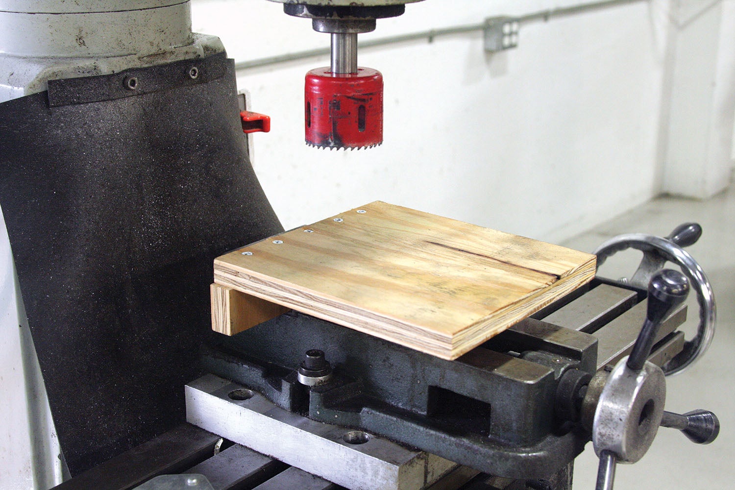
It’s sometimes possible to get around removing the vise by using a stage—a secondary table held by the vise itself. A stage can be an L or T shaped and made out of just about any material; I used scrap plywood to make an L-stage for this project. Most of the time a stage won’t be as rigid as the mill table (which rules out heavy side milling), but for drilling or boring, a stage should work fine.
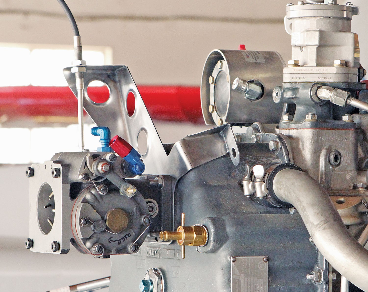
I recently helped Conrad Norquist of Riverside, California, with a custom throttle and mixture cable bracket for his RV project. The standard bracket was designed for a carburetor, but he needed a bracket that would put the cables in better alignment for a fuel injection throttle body. The factory bracket was made of 16-gauge steel sheet and powder-coated. Conrad had cut off the cable mounts and used some aluminum angle to reattach them in a more optimal location. This modified bracket was the template for making a new one.
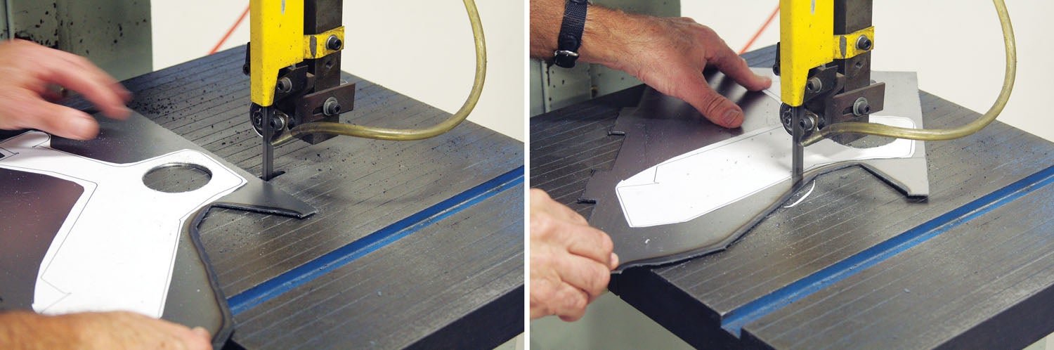
Making the pattern from the modified bracket was a simple matter of folding paper over the original and tracing the outline. With a paper template, you can either trace that pattern (called a flat pattern) onto your sheet metal or Spray Mount it to the workpiece (I like to Spray Mount patterns whenever possible). From there it’s off to the band saw or nibbler or however you like to cut out sheet metal parts.
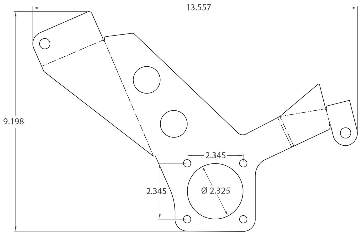
The RV cable bracket gets mounted between the intake and the carb—or in Conrad’s case, the throttle body. The intake port measures 2.325 inches in diameter and is surrounded by four holes for the mounting studs. These have to be precisely located. If the mounting holes are not positioned accurately relative to the intake, you could end up with a misalignment that might cause the engine to run poorly.

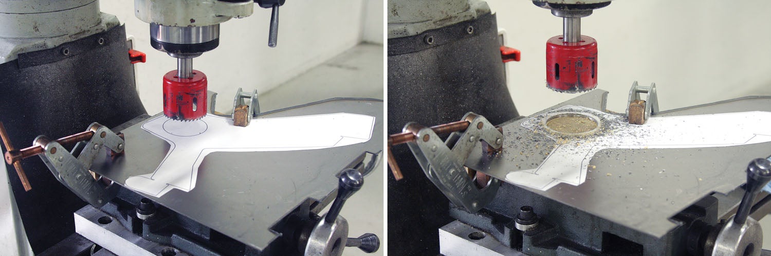
The size and odd shape of this bracket made it a perfect candidate for using a stage in the mill vise. I used a set of welder’s Kant-Twist clamps to firmly cinch the sheet to the stage. With the workpiece secured it was a simple matter of centering the cutter over the layout and, using a 2-1/8-inch bi-metal hole saw, making the opening for the intake. I then used the original bracket to line up and drill the holes for the mounting studs. With the holes drilled, I bolted the original to the new bracket and used a spindle sander to enlarge the intake hole to match the original.
I used a 1-1/8-inch Findlay punch (see “Findlay Punch,” February 2020) and a shop-made dimple die set (see “Power Polishing Promise,” March 2020) to knock out and dimple three lightening holes. The goal of these holes was to take some weight out of the part, but it also added a nice cosmetic touch.
Next time you come across a project that’s a bit awkward or impossible to clamp in the mill vise, remember the stage option!


Thanks, Bob. The plywood 2ndary stage is a GREAT idea. A bonus tip, using a holesaw in MDF was creating a bit of a burned ID; I started using a vacuum with a crevice tool right next to the holesaw to suck out the fine sawdust and took ‘pecking’ cuts to allow sawdust removal, and boom! Clean, much more consistent MDF holesaw holes and NO burning.
Comments are closed.