The terms “margin of safety” and its related term “factor of safety” are worth discussing since they are often misunderstood. They have specific meanings in the structural engineering of an aircraft. For starters, let’s shorten the terms: Margin or “MS” means margin of safety and “FS” means factor of safety. Margins are calculated for each part of the structure and often for several places on the part. Each margin applies for one specific load condition, one location on a part, and one mode of failure.
The equation for the margin of safety in its simplest form is:
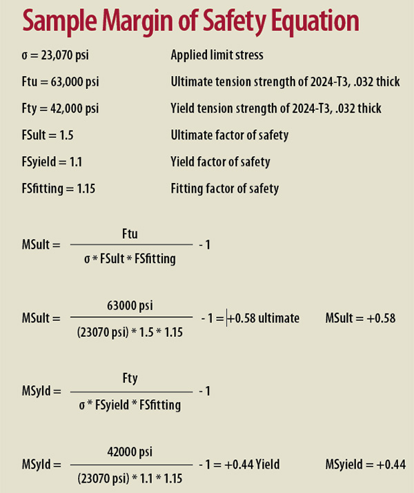
The terms of this equation must be consistent. The units have to match and the load or stress conditions need to be equivalent. The factors of safety, which have no units, are often used to make the conditions match. For example, the ultimate tensile stress of a material can be used with the limit stress on a part and an ultimate factor of safety. The result will be the ultimate margin for that case:
When the margin is exactly zero, it means that, while the strength is adequate, there’s nothing beyond that. There’s no reserve. But since the strength is adequate, whatever is being described by the margin is acceptable for that specific condition. When the margin is positive, that means that the condition has some reserve strength, which is why it’s called a margin of safety, and when it’s negative it means that the part is not strong enough.
When we’ve done the calculation and have the margin, it’s always shown with either a + or – sign as in this example:
People often underline them, too, to make it easier to spot on a page of calculations.
The major structural strength requirement for an airplane is that it must not fail at “ultimate” load and must not have, as the FAA elegantly and precisely puts it, “detrimental, permanent deformation” at “limit” load. Limit load is a very important phrase that means the maximum load on a part after considering all of the load conditions that might affect it. In the MS equation on the previous page, the applied load or stress is always limit load or ultimate load. There’s usually no point in checking a part for some load that’s less than limit, is there?
Calculating Margins and Load Limits
Every part that’s important gets analyzed and a margin calculated for it. Somewhere in the analysis report, usually as an appendix, there’s a long table listing all of the parts and their margins, and the loads that produced it. The fasteners that attach the part are analyzed, too, as well as the holes for them.
The loads might be aerodynamic, they might be landing loads, or they could be loads that a pilot applies to the control system. They might be from the operation of an engine, or even from a combination of applied loads acting simultaneously. The engineer has to consider every possible load case that affects a part and decide which one is the worst. That’s the load called limit.
The strength often comes from books like MMPDS, Metallic Materials Properties Development and Standardization, which gives material properties for the metals commonly used in Experimental (and certified) aircraft, as well as the fasteners. It also includes a bit of data about tubes, welds, and cables. And it has an excellent first chapter describing how the data is meant to be used, plus a later chapter about statistics. While this is excellent data, it’s often not all we need because aircraft usually have some parts that are “critical” in buckling. Buckling strengths need to be calculated for each specific circumstance, and other articles later in this series will delve into that. Or a part might be critical in bending, and we’ll need to determine the strength in bending.
Critical means that’s the condition defining the limit load. An engineer might say that the limit load is 1,800 pounds, for example, and that the part is critical in buckling, or that the critical case is the negative G-load case. Typically we don’t know what the critical case is until we’ve considered all of them.
Some materials like plastics and composites aren’t in MMPDS, and we’ll have to scratch around for data for them. When we’re doing that, remember that just as we found the highest possible load case, we need to find the minimum strength that materials might have. Since many commercial data resources list typical properties rather than minimums, we might need to dig a bit.
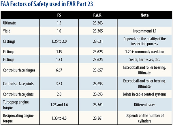
Factors of safety cover many things, but the most important is to define the ultimate case. For general aviation aircraft, the factor of safety for ultimate is 1.5. It can be greater when appropriate. A good example of this is that for composites, we might use a factor of 2.0. In aircraft, the factor of safety for yield is 1.0 but that means that a credible maximum load—limit load—can cause some detrimental, permanent deformation if a part has a zero margin in yield. In spacecraft, there’s an explicit yield factor of safety and a requirement that the engineer show that the yield margins are positive. The yield factor of safety is usually 1.1 or 1.2, and I think that a factor of 1.1 in yield is reasonable for aircraft, too.
Factors of safety that the FAA has used in Federal Aviation Regulation Part 23—Airworthiness Standards for Normal, Utility, Acrobatic and Commuter Airplanes—can be seen in the table. While Experimental aircraft are not required to use these factors of safety, I can’t see any reason to use smaller ones. It’s worth browsing through Part 23 (it’s online) to see the places and conditions these factors of safety are used.
Engineers also use factors of safety to add conservatism where they feel it’s needed. In this case, conservatism isn’t political—it’s the way we make sure that we hedge against things we’re not sure about. For example, if we’re using typical material properties rather than minimum, include a factor of 1.25 for that. If we’re not sure of the load case, use a factor, usually 1.2 to 2.0, to make sure that the end result is still safe. While we’re doing the analysis, we use whatever other factors of safety we feel are necessary and list them in the analysis and explain why we’re using them. We don’t need to write a book about it—a typical note might be “FS for loads uncertainty: 1.33.”
Factors of safety are almost always equal to or greater than 1.0. The entire purpose of the factors of safety is to bias the analysis so that instead of predicting the failure load, it predicts the maximum rational load at which there will be no failure. That can be an issue, because sometimes the question arises: What is the magnitude of load at which the part will fail?
We can’t predict that—we have to test for it. Failure will occur at a higher load than we can predict because all the loads are the maximum, all the material data reflects a minimum strength batch of materials, and all the analysis techniques are conservative.
Now we do have to be reasonable about it—we can’t just include a factor of safety of 100 every time, knowing that if we do, the part can’t break. If we do that, the airplane will be too heavy to fly. We try to tread a road called truth, but we stay on the side marked safety.
If there is more than one factor of safety, they should all be put into the equation. They don’t add—they multiply, as shown below.
It’s good to remember that the simple form of the margin of safety equation that we’ve been discussing is the most common, but there are times when more than one load occurs on a part at the same time, and the part has to carry both loads. This gives a more complex margin of safety equation than the simple example here, and it’s worth mentioning that different types of interaction are, in their details, handled differently. Here’s the basic concept.
“R” is the symbol used to mean a load ratio. A load ratio is
Although it’s similar to a margin of safety, it’s not. Don’t get them confused.
Let’s say that we’ve got a part and a load case that combines tension with some shear. We’d find Rt for the tension load ratio and Rs for the shear load ratio, including the factors of safety as needed. Then these load ratios combine like this:
It’s important to remember that while this works for tension, compression, or bending—any one of these—combined with shear, most interactions don’t use this particular equation, so we’ll have to look them up. But the concept of finding the load ratios and combining them in a particular manner is generally appropriate. Remember that the factors of safety go into calculation of R.


hi is there any citation reference or publication regarding with this