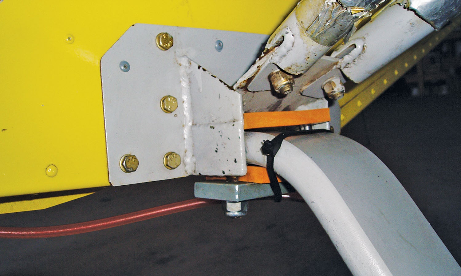
The main landing gear on the Zenith STOL CH 701 is sandwiched between the gear/strut fitting and the gear plate, but separated top and bottom with flexible spacers. Originally, layers of inner tubes were specified. Later I used automobile heater hose that had been cut lengthwise. The heater hose only worked for a while and then wore through at the upper contact point. Fortunately, Zenith now offers polyurethane spacers (Part Number 7L2-2A/1) that are fairly hard but still flexible. Here’s how I installed them on N701TX, my STOL CH 701.
First, I built a main gear jacking support. This tool is useful for more than upgrading the spacers; it also comes in handy when raising the airplane to remove a wheel for brake work, tire exchange, etc.
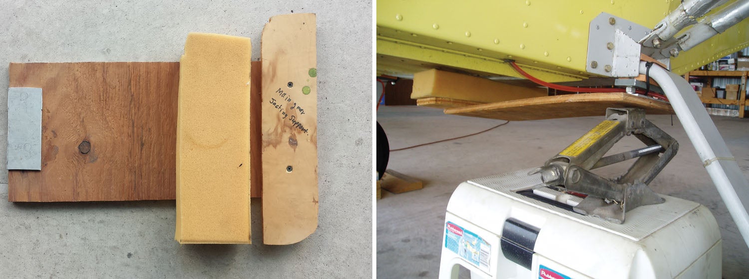

Using scraps from around the shop, I made the jacking support from a 10×18-inch piece of 1/2-inch-thick plywood, a 2×6-inch piece of 1/8-inch-thick aluminum plate (glued to the plywood), a second piece of 1/2-inch plywood measuring 3×12 inches and a piece of foam. The aluminum plate protects both the plywood and the 3/8-inch studs that are welded inside the gear/strut fitting. The foam protects the bottom of the fuselage.
After I built the jacking support, the next order of business was to chock the airplane on one side and remove the gear plate and bottom spacer on the other side. Warning! Do not remove the gear plates on both sides at the same time.
Place the jacking support and a jack under the 3/8-inch studs. You can now safely raise the airplane to gain access to the top of the main gear under the gear/strut fitting. The wheel will stay on the ground as the airplane rises, exposing the old top gear spacer for removal.
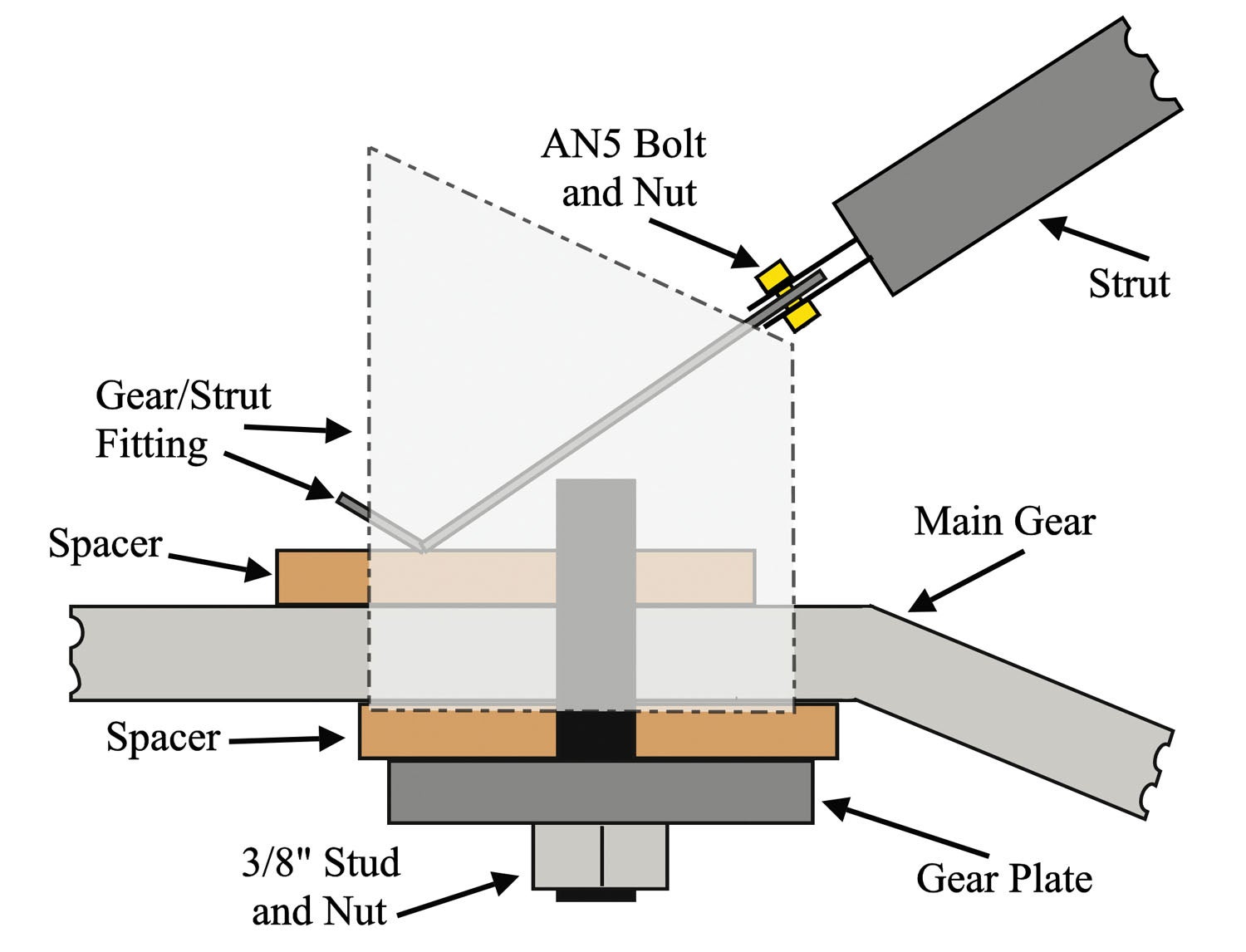
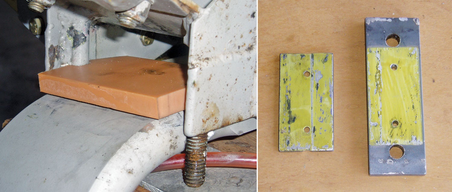
You may have to trim the new spacers to fit inside the gear/strut fitting and notch them to go around the 3/8-inch studs. The upper spacer notches are not centered, but are offset to reasonably place the spacer under the main load point of the gear/strut fitting. I trimmed one corner of the upper spacer so I could work it into place between the studs. Once the top spacer is securely positioned on top of the main gear, lower the jack so the airplane is resting on the wheel.
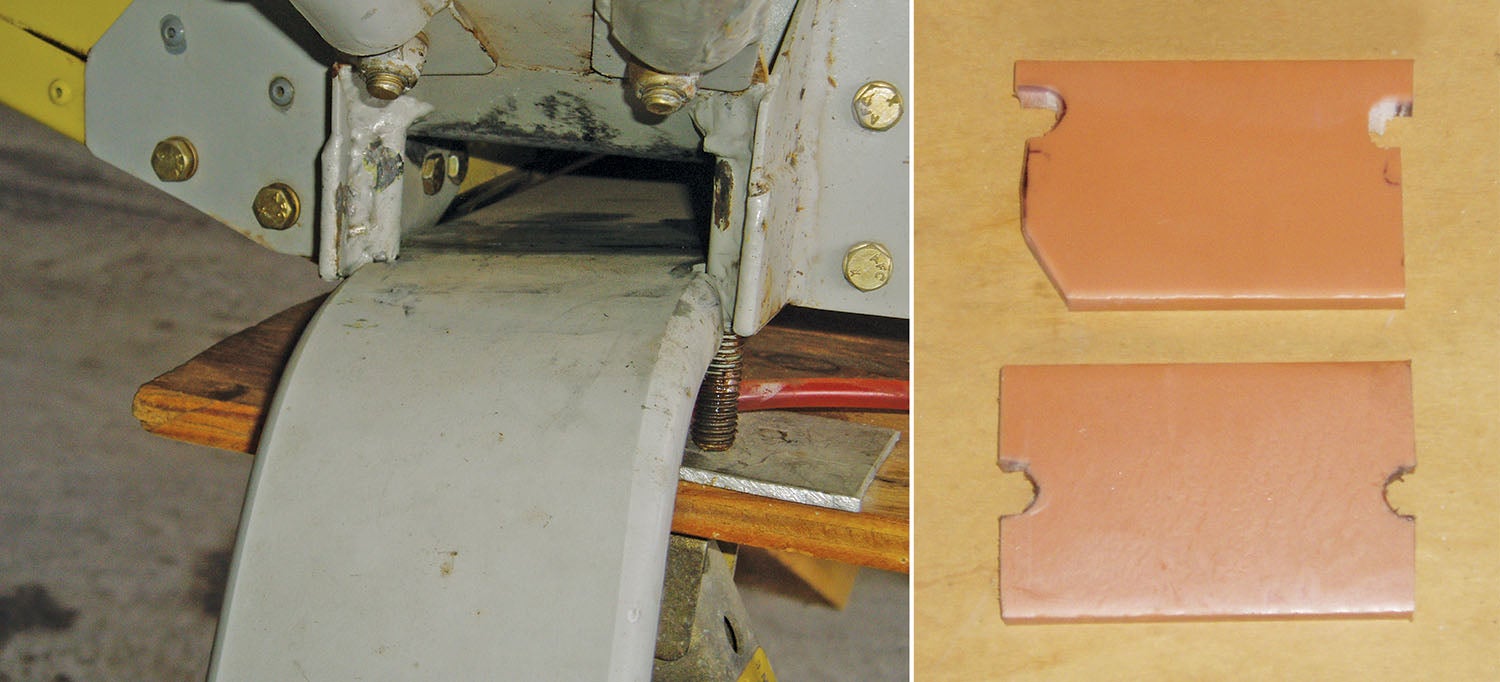
The new spacers are fairly thick, thus on N701TX the upper piece of my gear plate had to be separated from the bottom piece. This was simply done by drilling out the rivets.
Next, install the bottom spacer and gear plate and you are finished with the first side. To complete the polyurethane spacer upgrade, repeat the process on the opposite side of the main gear.
![Coming in for a landing at Humberd’s Farm [All Images Credited to Jon Humberd]](https://www.kitplanes.com/wp-content/uploads/2026/07/9-1.jpg?w=218&h=150&crop=1 "Overcoming Setbacks on the Zenith 750SD Xtreme")
![[Credit: Zenith Aircraft Company]](https://www.kitplanes.com/wp-content/uploads/2026/06/31142685469.jpg?w=218&h=150&crop=1 "Zenith Throws Open Its Doors for “Fly-In to Summer”")
![Members of the North Idaho High School Aerospace Program gathered at KSZT [Credit: North Idaho High School Aerospace Program]](https://www.kitplanes.com/wp-content/uploads/2026/02/IMG_3499.jpg?w=218&h=150&crop=1 "North Idaho High School Student ACES Fly the Aircraft They Built")


Thanks, when I moved my 750 form the house to the hangar the top pilot side rubber worked its way out of the pocket wile on the trailer, I’ll use your wood lift design to get it back in. but I’m thinking of replacing it with some thicker 85 duro rubber pad cause the polyurethane spacers seem a bit crumbly.
I replaced my 3/8” orange polyurethane spacers with some 1/2” thick rubber I bought from McMaster-Carr. It comes in 6”X12” strips and the Durometer rating of 55 worked well. The Urethane spacers became brittle and fell apart after about 6 or 7 years..
Chuck D.: thanks for highlighting your approach to “spacers” in the Zenith Landing Gear. My question “why the spacers?” Does the landing gear mounting process allow for a “gap” for which a spacer is required 0r have you found a “gap” and fill it with solid poly-fillerpad or shock absorbent material (rubber, hose). What’s the purpose of needing any filler in this design using this one piece Landing gear? and is there any alignment or lateral shift preventive method also employed (centering bolt center of fuselage thru landing gear)? Im building an aerobatic airplane, with single piece aluminum landing gear (Grove Aircraft), and wondering if I should modify my Landing gear attach method to allow for a shock absorbent material that extends (laterally) across the landing gear to reduce shock-stress on the fuselage? welcome hearing more about why this design requires a gap fill of some type that you and others are using with landing gear on Zeniths. thank you. Mark Y
If you look at the last set of photos, you can see 3/8″ studs on the gear/strut fitting. The aluminum main gear is notched to fit between these studs which stops any lateral movement. I am not sure about the reason for the spacers, but they were in the 701 plans. I suspect they may absorb any shock and also prevent wear on the aluminum gear contact point as the gear flexes at landing.
Comments are closed.