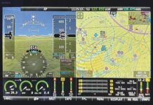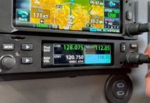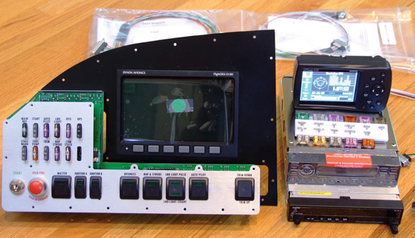
The expensive pieces of the RV-12 avionics package line up, awaiting installation. From left to right and top to bottom: factory-built control panel, Dynon D180 EFIS/EMS, Garmin 496 GPS, Garmin SL40 com radio and Garmin transponder. Not shown are the Flightcom intercom and Artex 406 MHz ELT remote switch.
The first four installations of this series covered building the kit segments to complete the entire Van’s Aircraft RV-12 airframe. That included starting with the wing/flaperon kit, followed by the empennage and tail cone, forward fuselage and finally the finish kit, which comprises controls hookup and adjustment, landing gear and brakes, fuel tank, canopy, completely finished seat cushions with the customer’s choice of trim color, two-piece engine cowl, and wiring including bracketry and cabling for the optional Dynon autopilot.
It’s worth a reminder that this is one of the first RV-12s built, and also one of the first Experimental Light Sport Aircraft (ELSAs) based on an FAA-approved Special Light Sport (SLSA), the red kit prototype seen at many events over the last year.
Black (and Gray and Yellow) Boxes
The avionics package became available as the fifth kit segment. This section requires the least work and the most money so far. And because ELSA builders must duplicate the FAA-approved SLSA model, it offers the first real choice: The builder chooses from among Garmin GPS models 296, 396 or 496. The highest-price option Garmin 496 offers the chance to spend even more money on an exceptionally valuable feature: near-real-time weather from XM Satellite Radio superimposed on the unit’s terrain-displaying moving map. At the time I wrote the big check for the Garmin 496-equipped avionics package, the total came to well over $13,000.
The other black and gray boxes and systems included the Dynon FlightDEK-D180 EFIS/engine monitoring system (with built-in software for the single- or two-axis autopilot), Garmin SL40 com transceiver, Garmin GTX 327 transponder, Flightcom stereo intercom, and a bright yellow Artex 406 MHz ELT.
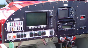
Tying these units together is a factory-built custom control panel with switches for master power, engine start, optional nav and strobe lights, autopilot and electric pitch trim. The control panel is made for Van’s by SteinAir, in Minneapolis, and all avionics units, trays, cables and antennas are shipped from SteinAir to the builder. Van’s supplies the few metal parts—antenna and magnetometer brackets, for example.
A bold-print letter from SteinAir notes that avionics problems should be addressed to that company rather than Van’s Aircraft. Also stressed is that programmable units such as the Garmin GPS, radio, transponder and the intercom have been tailored specifically for the RV-12 system and should work without additional effort by the builder when they are powered up. In other words, don’t apply volts to any of the units, and don’t do anything with them until instructed.
The Garmin GPS is the exception. It comes equipped for automotive and marine use in addition to its default aviation function and may be used in those modes without fear. (I’m writing this while on vacation in Sunriver, Oregon, a resort community with 13 traffic circles. We enjoyed accurate commentary from Bernice, the “Babe in the Box,” as she guided us perfectly through the roads and circles to our leased house.)
Let’s Get Started
Getting through the first full page of instructions takes just two steps and 5 minutes: Cut and apply supplied labels to the back of the control panel for eight D-sub cable connections plus the power plug and five holes with calibration potentiometers behind them. Take the rest of the day off. Or continue the fun on the next page of instructions.
The left side of the instrument panel is removed so the control panel can be placed behind it and fastened permanently back in place. Fuses are inserted into their places on the top of the control panel, and spare fuses are set in their labeled slots in a plastic holder that is double-stick taped inside the map box door where it can be reached from either seat in the airplane. Clever!
The beefy shelf for the Dynon EFIS is attached behind the left instrument panel after clearing two of the attach holes with a file. The D180 may now be slid home in its shelf and locked securely with a supplied wrench. The static line and two EFIS cable connectors are fastened to the back of the unit. A 37-pin connector is routed to its home on the back of the control panel, and the connectors are secured with screws. Plastic backshells need to be attached to most cable connectors. This takes maybe a minute each after the first one or two.
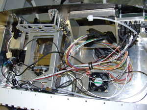
Com radio and transponder trays (left, along with the GPS dock) come with their wiring harnesses already installed. The Dynon EFIS tray also awaits its unit.
Installing the transponder tray (lowest in the radio/GPS stack) takes a bit longer and is followed by the transceiver tray above it. Wire cables and connectors come attached to the trays, and these cables with their connectors on the other end are to be routed for security through a previously installed cable clamp. That’s not a problem, as the clamp can be opened to admit new wires. However, they are also to be put through one or more plastic snap bushings installed in metal brackets. According to the drawings, brackets in the newer kits have cutouts to allow slipping new wires inside, but for the wiring to get inside the snap bushings, they must be snipped and the wires forced through the slit in the bushings, which are then reseated in their brackets. (Early kits like mine also require cutting the metal brackets to admit the additional wiring.) Transponder and transceiver wire harnesses are attached to their places on the back of the control panel. The cushioned cable clamp and the snap bushings should be left open until the intercom cable is installed.
Coax cables are already in place for the supplied transponder and com antennas; 8-32 hex nuts are reached through inspection holes on the bottom of the fuselage to attach the com antenna. The transponder antenna is fastened through its hole near the center of the belly, forward of the seats, but the panel covering the floor tunnel in this area must be removed to do it. Thirty minutes were required to attach these antennas.
GPS and Intercom Hookup
The Garmin external GPS antenna and an XM Satellite Radio antenna are screwed to a bracket high on the forward side of the firewall. Their coax cables go through the firewall. A heavy custom aluminum plate (ready for deburring, primer and paint) and aluminum tube standoffs hold the plastic Garmin GPS dock to the instrument panel.
Now comes another rare builder’s choice: Enlarge the GPS hole in the panel, make another slight factory-approved mod, and you can easily remove the GPS for theft prevention, programming waypoints at home for a trip or other uses (automotive or marine). Or you can leave the hole the original size, and the GPS is locked behind the panel. In either case, the GPS may now be snapped in its dock and its four cables attached. One of the cables goes to the control panel; the other three are antennas and power.
Next comes intercom installation, and there’s some actual wiring to do here. The small intercom box is easily screwed to the front panel, and its cable, minus the connector backshells, is made up…with an exception. Separate five-wire cables have been routed from the pilot’s and copilot’s headset jacks beside the left and right seats to an area near the rear of the intercom. Page 42-14, Revision 1, shows how these 10 wires are routed to the intercom.
Six of the 10 have factory-installed D-sub pins that are snapped in their designated holes through the back of the connector. The remaining two pairs are twisted together and connected. You may need a strong light, and I used a binocular loupe to see the tiny numbers on the connector. Even so, I snapped one wire in the wrong hole and made good use of the pin extractor tool supplied with the finish kit. After the correct connection is confirmed, a backshell is attached to the intercom cable, which is screwed to the rear of the unit. Like the radio and transponder cables, the intercom wiring is routed through a cushioned clamp and a snap bushing that must be snipped.
The ELT and Magnetometer
The avionics package comes with a 406 MHz Artex emergency locator transmitter (ELT), which is a good move because satellite monitoring of the 121.5 MHz emergency frequency has concluded.
The ELT antenna is mounted to a bracket that is attached with screws to a pair of nutplates installed behind the passenger’s seat on top of the mid-fuselage crossover brace. Holes in the bottom of the brace allow you to get the nutplates in position for pull-riveting them. The slightly angled antenna bracket, which goes just forward of the fuel tank, allows fixing of the ELT antenna with its hex nut and lock washer.
The plastic ELT tray and an aluminum bracket to hold the ELT buzzer are Clecoed and then riveted in place, and special wide-head pull rivets secure the tray to the right side of the fuselage. The ELT comes with a telephone-style connector adapter with red and black wires that connect to the buzzer, which is secured in its bracket. The ELT is strapped to its tray, and the white telephone wire with a modular plug installed much earlier is plugged into the adapter.
The other end of the white phone cable was previously routed to the instrument panel. It plugs into a short phone adapter that connects to the self-powered remote ELT switch that is bolted to the panel above the intercom.
Every instrument in the RV-12, including the magnetic compass, is displayed on the Dynon screen. Dynon’s magnetometer—the magnetic compass sensor—is attached to small brackets and pull-riveted from behind to the top of the aft fuselage ring one station behind the baggage/fuel tank area. A special D-sub backshell with non-ferrous screws is attached to the connector, which is plugged into the magnetometer.
What’s Next?
As this is written, the engine/propeller package has just become available. It includes the Rotax 912ULS engine, slightly ground-adjustable Sensenich composite prop, spinner, battery and other firewall-forward parts. A few more fiberglass pieces—engine and cockpit heat baffling—come with the power package, along with procedures for breaking in the Rotax after installation.
The FAA has confirmed that 3-inch N-numbers will be sufficient on the Experimental-category RV-12 and that as little as 5 hours of test flying may be needed before a final airworthiness certificate will be issued. For an ELSA such as this one, initial flying is the equivalent of production test rather than Experimental test flying. That’s because RV-12 builders sign a form that they are using all systems and building techniques found in the SLSA on which the kit version is based.
Depending on the timing, including an FAA inspection, the next episode just might include the first flight or two.
For more information, call 503/678-6545 or visit www.vansaircraft.com.

