Most milling machines have the capability to tilt the head to make angled cuts. This comes in handy when the workpiece can’t be conveniently clamped at the required angle or in instances where angled cuts on multiple parts require a higher degree of accuracy. Tilting can also be the key to making some interesting scallops, which could be used for utility or cosmetic purposes.
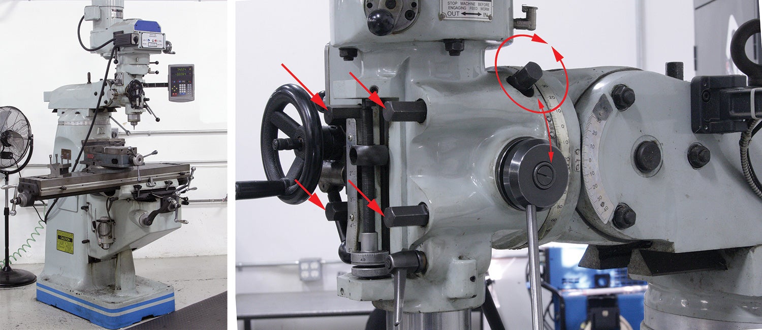
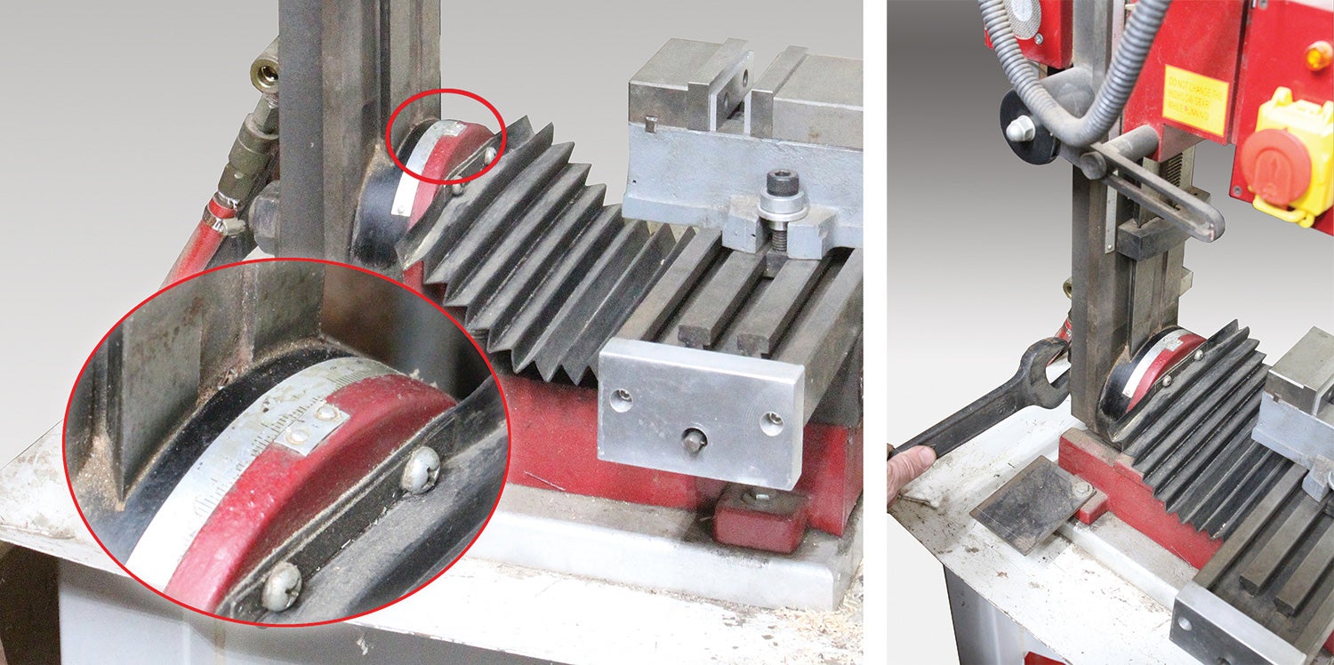
Tilting a milling head involves loosening clamping bolts and manually rotating or mechanically slewing the head to the desired angle and re-clamping the head. The head on a professional-grade machine like a Bridgeport-style mill is very heavy, so it typically incorporates a worm-drive mechanical adjustment. This makes it easy for a single operator to adjust, check, refine and lock the settings to the nth degree. You won’t find a worm drive on smaller home-shop or benchtop mills. But they’re relatively light weight, so it’s no problem to manually nudge the head to a precise angle.
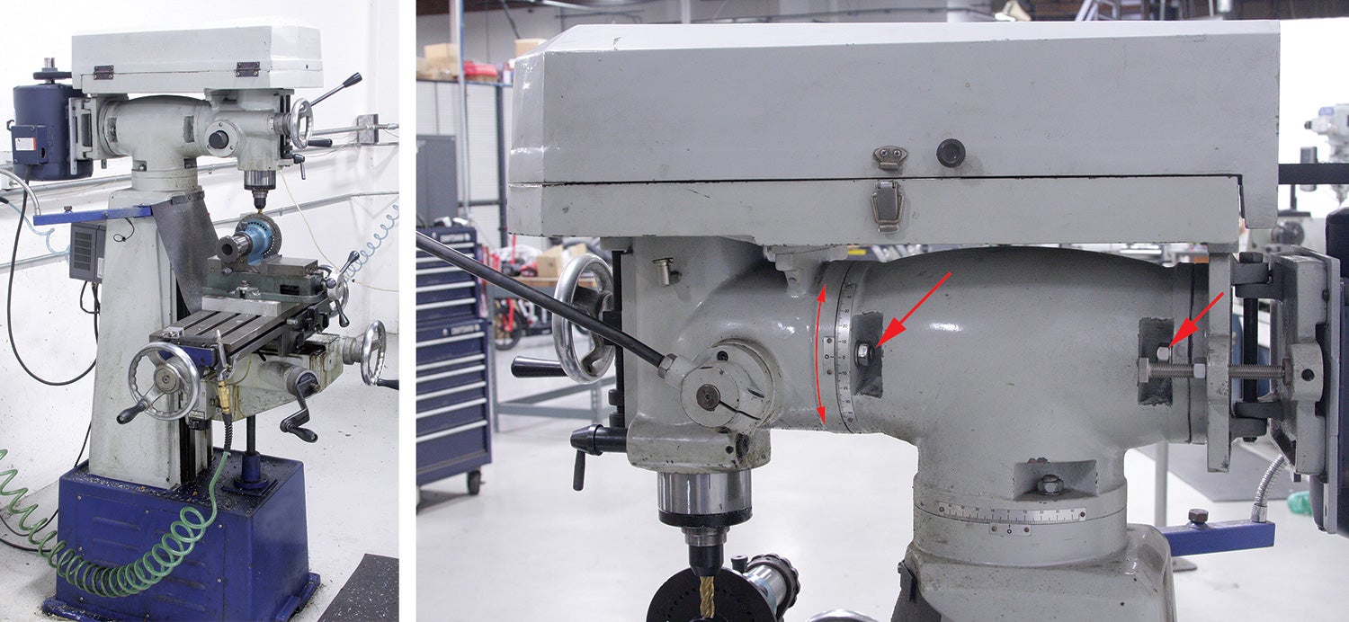
Most small home-shop mills tilt only left and right (some don’t tilt at all). While this may appear to be a major limitation compared to the fully articulating head of a Bridgeport mill (which tilts left and right, forward and back, and swivels), the reality is, you’ll rarely encounter a job that requires more than one direction of tilt.

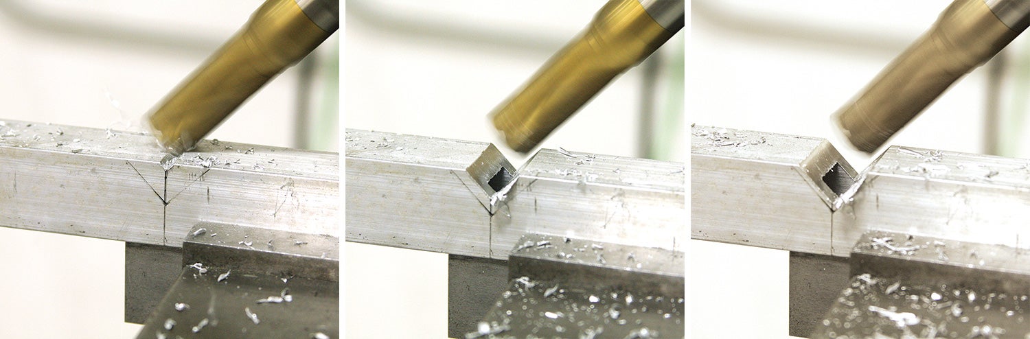
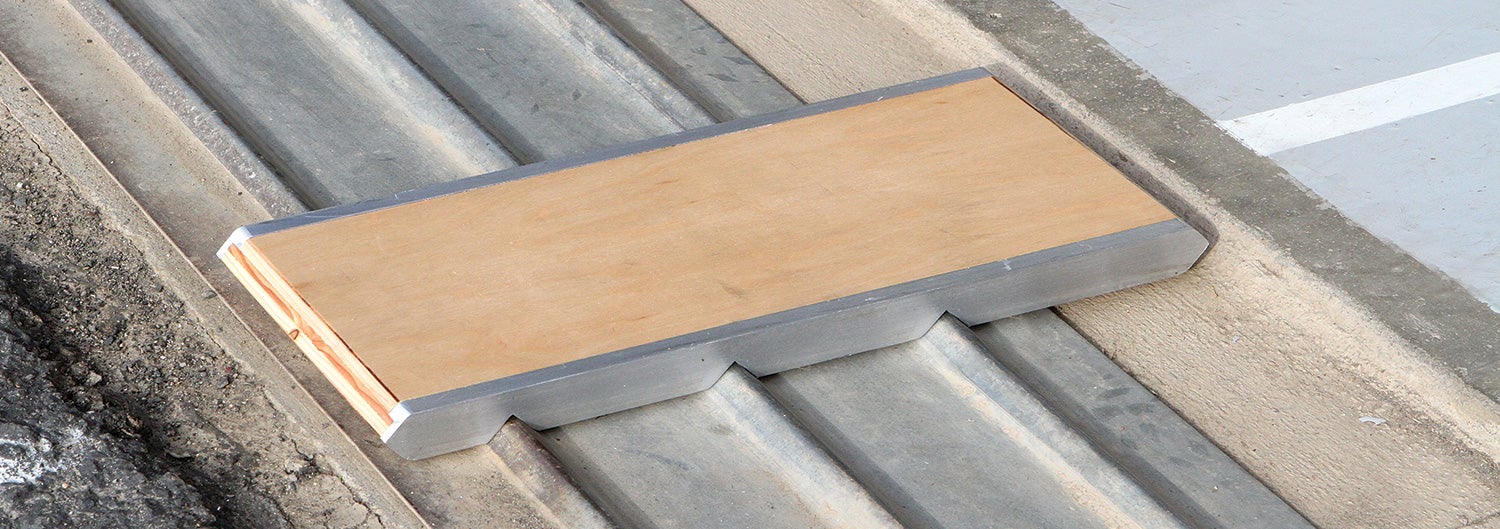
I recently had occasion to use the tilt function to mill a series of notches into a 1x1x0.20-inch wall aluminum square tube. The part was being made to upgrade the plywood threshold ramps for my hangar. What’s a threshold ramp? It’s a small board that goes over the door tracks. These tracks are, unfortunately, just the right size (or wrong size, as the case may be) so that when I’m pushing my Jabiru into the hangar (without the ramps), unless I get a good run at them, they stop the plane dead. My plywood ramps were getting old and recently one of them delaminated. So I decided to upgrade to new ramps with aluminum side supports.
Making Scalloped Grooves
This next method is a neat trick if you need to mill a scallop or radius that’s bigger than your largest cutter.
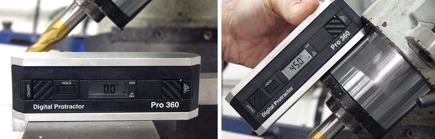
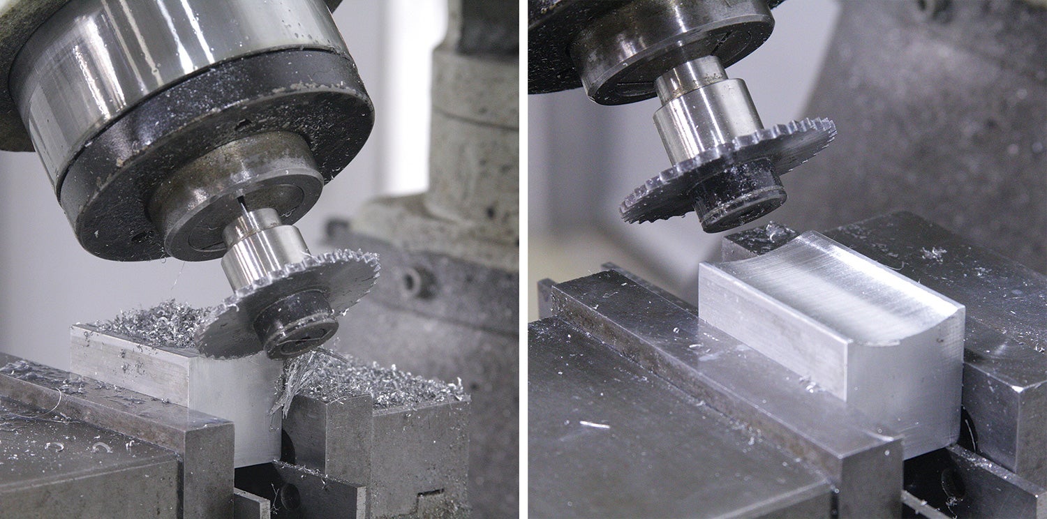
The concept is simple enough: Imagine if your milling head is set square to the table and you install a two-inch-diameter face-milling cutter, such as a fly cutter or large end mill. Clamp a 1¼-inch-wide workpiece in the vise. If the cutter really is perpendicular, any single-path pass you make across the top of the workpiece (often called a planing cut) will result in a dead-flat surface. Now imagine the mill head slightly out of adjustment (tilted). Instead of a planing cut, the surface will be dished as a result of the skewed cutter angle.
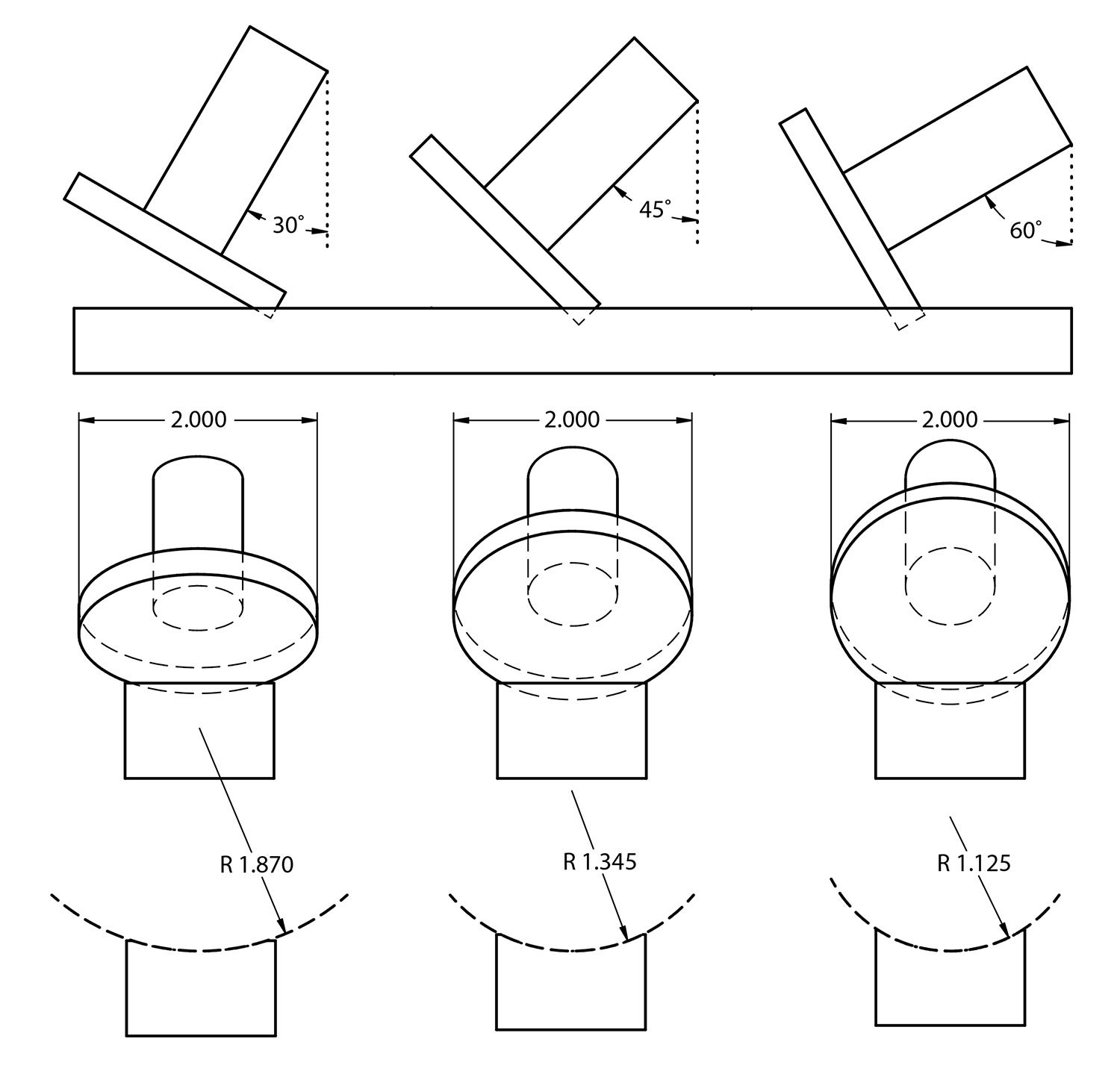
The idea is to take advantage of this “error,” which can be used to make a scallop or radius in a workpiece that’s larger than the diameter of any cutter. The accompanying illustration shows how using a two-inch cutter, you can make a variety of different radius-type cuts, all of them larger than the 1-inch radius of the 2-inch cutter. Upon close examination, you will notice the resulting scallop is actually a segment of an ellipse and not a true radius. For the sake of illustration, I superimposed the ballpark radius that you would get using a 2-inch diameter tool.
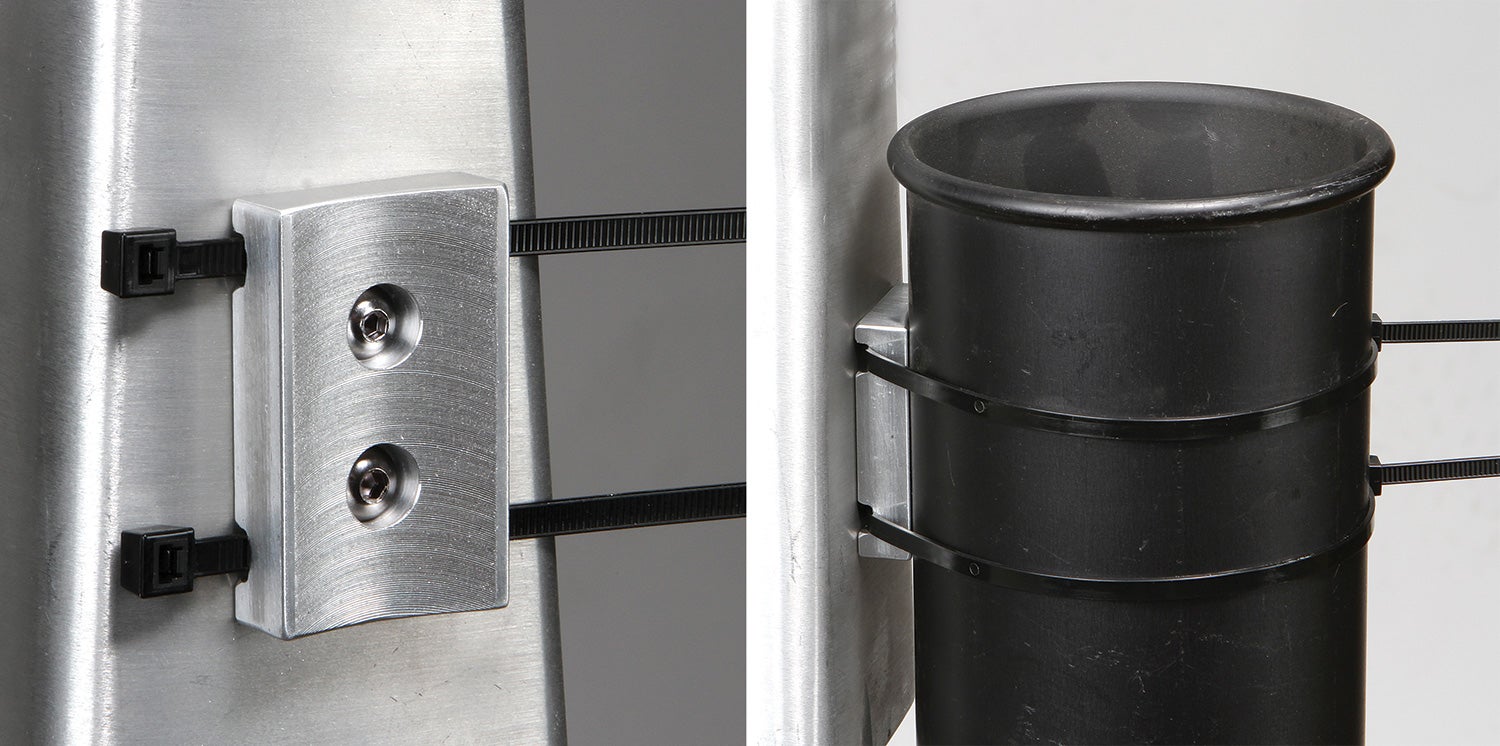
This technique is invaluable for making brackets and mounts for large-diameter objects like oxygen tanks or oil collectors. CAD software like SolidWorks, Solid Edge and Inventor make it easy to work out which angle and cutter to use to get the groove you want. But you can also figure it out through trial and error using scraps of wood, plastic, foam blocks or anything else that’s expendable. If you’re a math geek and actually know what all those Greek symbols mean on the calculator, you can figure it out that way, too.
Another option is to go to a website called Marv Klotz’s Utilities and look for a program called Radius.zip. Scroll all the way to the bottom and you’ll find it under the heading “Submitted Software.” The program was written by a Virginia-based naval engineer named Steve Horace. The description sums it up perfectly: “An old trick for cutting a shallow groove of non-standard radius is to use a standard size milling cutter with radius less than the groove radius tilted to an appropriate angle.”
That’s it for now. Time to get back in the shop and make some chips!


Hi Bob,
I read with interest your suggestions, clear and useful, but I have a doubt regarding the radius obtained tilting the mill head:
It is a circle or an ellipse?
Claudio
It’s an ellipse.
In the text I mention:
Upon close examination, you will notice the resulting scallop is actually a segment of an ellipse and not a true radius. For the sake of illustration, I superimposed the ballpark radius that you would get using a 2-inch diameter tool.
Thanks for the comment!!
The section of the generated ellipse will depend on the depth of the resulting groove. Different depths will produce different simulated radii using the same angle. This is assuming that the curve passes through the end points of the arc and the midpoint.
There is an explanation here – https://youtu.be/DFhbjyG3Bqs
Comments are closed.