By my sixth month of building I’d battled with and conquered the firewall sheet metal, slain the master cylinder, subdued the twisted tail and even managed to vanquish the dreaded elevator horn. I was gaining a sense of confidence with fiberglass problem solving.
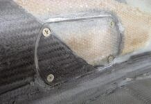
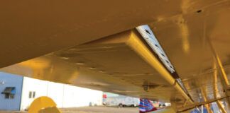
And a good thing, too. I’d been in contact with some other Jabiru builders and was cautioned that where the directions say to drill for a gas cap is too far forward; you’ll take a nice notch out of the wingspar. So I carefully measured the position for the hole and then did as Don French suggested, “Darken the workshop, and put a really bright light under the wing; you’ll see everything.” He was right. I saw that my layout would have cut right into the mainspar!
I moved the hole about a half-inch aft and met with only partial success; the fuel tank has a curved upper edge, so I was not fully onto the flat as I should have been. A judicious packing of flox was sufficient to rectify the problem.
The caps themselves are odd and come in three pieces: cap assembly, tube and a neat little machined fitting that looks like a piccolo. What they don’t come with is a clue to how they’re put together. A call to Jim McCormick, the West Coast Jabiru distributor, solved it, and a careful use of the lathe and tailstock as a press assembled it.
In Search Of…
The trick was to determine which way those holes in the uppermost piece should fit. Thinking through their purpose led me to a solution. On the ground those tiny holes allow heat-induced expansion or contraction of the fuel and air within the tank. With the aircraft stationary, which way the piccolo faces is unimportant.
What is wanted in flight is a way for air to come in as fuel is used. So, if the holes were facing aft or sideways relative to the airstream, I’d have a partial vacuum around those holes and a possible siphon. Facing forward, they would tend to pressurize the tank by a miniscule amount, but bugs might block the holes. The tanks are interconnected, and there are multiple holes in two of these cap assemblies, so that seemed unlikely, and forward it went.
The caps don’t have handles as do those on, say, an RV. They work the same way though: Two plates are squeezed together to expand an O-ring against the seat of the cap. The RV guys can push down a lever to squeeze the plates together. Jabiru squeezes the plates together with an Allen screw. At first this looks a bit cheesy, but on examination, it’s quite neat.
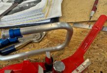
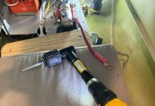
It occurred to me that the only part of the wrench being used as a wrench was the part that fit into the bolt; the rest of it is a lever. So I cut a quarter-inch off the wrench and welded that stub to the side of my ignition key. Like the RV types who use their ignition key, I have to use a tool to remove the cap, but this cap costs a lot less, doesn’t risk a bent key and doesn’t scratch the cap. Nicely done.
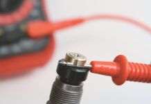
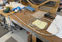
The ring into which the cap fits has to be grounded as well. The wings are non-conductive, so you have to add a ground by running a 6-foot-long vent tube from the wingroot, through the wing/tank, out to the cap ring, and then attach that tube to the cap ring. That stub of tube at the wingroot is then connected to tubing that you run down to the header tank under the right seat. While you’re at it, run a ground wire from the tube stub on a parallel path, but take it all the way to the engine. Reaching through the gas cap to start a screw is a little tough, but it seems to be a good system. It’s easier than it sounds. You now have a vented and grounded fuel tank—on one wing. Do it to the other wing, too.
Fiberglass Flaws
Fiberglass, with all its advantages, also may have flaws that are not immediately apparent. One flaw stood out: A wing had an odd bump that I couldn’t help poking. Flexing it indicated a dry spot. That is, when the layers were put together, this area didn’t get any epoxy, so it moved easily.
At first I was appalled, but further thought suggested it was inconsequential. How is it different from drilling a large hole? This assumes that it’s a localized defect, and careful inspection indicated that was the case.
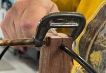
McCormick flew up to take a look. “I can fix that!” he said, and whipped out a hypodermic syringe. Euthanasia? No, he would just inject some epoxy below the surface. The needle was not strong enough to get through the outer surface, so he punched a series of small holes with a trammel point, and then simply injected the epoxy until it came out the vents. After it hardened I sanded it down, and I have to say that it seems to be a nice solution.
Careful examination of the wings, however, revealed another problem, albeit not a safety concern. The upper surfaces look more like a tube-and-fabric assembly. During construction, the still-wet skins apparently sank down between each of the ribs, and it will require copious filling to level it all out.
Bill George, my neighbor with a Lancair IV-P, says that he did not see this on his Lancair 360, but that was because he closed the wing himself and was careful to keep the surface flat. Me? I’m going to acquire stock in the company that makes Superfil. I’ll be buying a lot of it.
Moving out to the end of the wing showed the wingtips to have an annoying and unnecessary surface defect. It’s easily fixed, but would have been more easily avoided at the factory. What looks like wrinkled fabric is exactly that. Proper vacuum-bagging procedure includes the use of a pad between the bag and the components. Leaving it out puts the wrinkled bag in close contact with the semi-liquid surfaces and results in a hardened finish resembling wrinkled sheets. Superfil and sanding will fix it, but I pulled a wingtip off the shelf from an RV and had to wonder just which part came from the metal airplane builder and which came from the fiberglass expert.
On the Nose
Last month I put the stainless steel on the firewall so now let’s put the nosewheel and front suspension together. In working with a glass airplane you get accustomed to thinking of paint as being last. Here, though, you have to paint the parts first.
You may remember an item in “The Home Machinist” series that spoke about using a lathe to cut a bit off an axle spacer. The then-unnamed source of that material was Jabiru, which had recommended grinding it off. If you don’t have a lathe, that’s what you’ll have to do. It’s a simple job in either case, but be aware that if you neglect it, your bearings will be overloaded and are likely to fail.
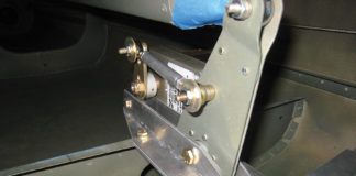
With the suspension system it’s best to get a good idea of how all the bits are going to assemble because compressing the red plastic spring is really a two-person job, so it’s not subject to a dry-run assembly. The directions were pretty good, and with some help it went together nicely. Assembling the mount itself was a minor puzzle even though what was sent was not what was depicted in the instructions and drawings. Installing the mount was fraught with hazard. Check the vertical placement on the firewall carefully. Had I done as directed, there would have been no clearance for the nuts on the cabin side.
I drilled a single hole to get the right height, and then, using a good digital level, aligned it and drilled the other three holes. Once it’s in place you have to drill two more holes in the firewall for the steering control rods, so don’t tighten the bolts just yet. Installing the rest of the nosewheel, and then projecting straight back to the firewall showed exactly where the rods would go through. We had already put the rudder pedals in, and there was simply no way to confirm the right location. It’s like digging a tunnel from both sides of a mountain and hoping the two crews meet. I drilled an eighth-inch hole and inserted a wire to see where it came out, and then I simply enlarged the holes.
Rigging the Spring
Jabiru has changed the configuration of the steering spring mechanism several times, so once again the hardware didn’t match the directions. McCormick’s Jabiru has coil compression springs on the engine side of the firewall; mine came with a bag of parts that included four extension springs. I have earlier mentioned being puzzled by what looked like springs from the rear wheel of a taildragger. I was right in that they are for directional control of the landing gear—just on the other end of the airplane. They are installed between the center console and the rudder pedals.
The method of rigging leaves a lot to be desired. Mounting one end of multiple springs on a single post is OK, but you should never do so in a way that allows the coils of one spring to touch the coils of another, which risks having the two springs merge together when extended and then be unable to contract. I rigged up a triple-tree to avoid this. It keeps the springs parallel, separated and balanced in their tension.
I was not happy with the way Jabiru wanted to secure the other end of the springs, either. The factory supplied a 10-inch-tall U of aluminum to be bolted to the console. That might work if the console were heavier material, but with this much leverage it seemed likely that the stresses would cause elongation in thin fiberglass. I discarded that U and fabricated a backing plate, a mount, and used multiple attach points that distributed the load. While it will work, I am not fully satisfied, and I will be tearing it all out and replacing it with a pair of gas springs. If you see someone at the airshows with his head under the panel, studying brake pedals while the rest of the crowd focuses on the glass panel, say hello. Fortunately, fiberglass is a forgiving medium that allows you to fix a lot of defects.
The Wingman Cometh
I had the wings on sawhorses and kept thinking that something wasn’t right every time I walked past the wingroot. Finally, I stopped and looked closely; the wings are held to the fuselage with two bolts. That seemed adequate. After all, the B-52’s wings are held on with only two bolts. They’re 8 inches in diameter and this little airplane doesn’t weigh 400,000 pounds, so that’s fine. What’s not fine is that these four bolt holes are three different sizes! And one of them is drilled too small—and off center.
Ron Wright had a similar problem with his Jabiru. The wings had different angles of incidence, and the plane kept turning to the right. He had to remove the wings, pull the bushings out, make new ones that were drilled off-center so he could rotate them to tweak the angle of the wing, and reinstall them. And he had his original bushings!
It was simple to use an E-Z Out to extract the one that was drilled off-center, drill one of Wright’s to the proper size (for some reason his used smaller bolts), and screw it back in to the wingspar. The undersized ones were drilled in place. We wouldn’t know if the wing incidence matched until the wings were installed, but at least I could now bolt the wings on. As it turned out, the incidence of the two wings not only matched each other, they matched Wright’s plane.
Next month we’ll hang the engine, and install the windows and doors.
For more information on the Jabiru J250, call 559/431-1701, or visit http://www.jabiru/pacific.com.

