I know most everyone flies IFR with belt-and-suspender tablet-computer backups, but let’s be real: Total and even partial EFIS failures in the clag or at night are no joke. And since most otherwise skilled builders aren’t trained avionics techs with years of install and troubleshooting experience, the chances of having to deal with (and fix) an installation screwup are good. Even if you didn’t build the kit and inherited someone else’s work, with a little bit of savvy, a lot of concentration and the proper manuals and wiring prints, you can get it fixed right to last a long time.![]()
For a follow-up to the Troubleshooting 101 article in the August 2021 issue of KITPLANES®, here we’ll focus on common EFIS problems. We’re talking about heading error, air-data and angle-of-attack and attitude problems, plus some things to do to make the system easy to troubleshoot as it ages. As a bonus, Garmin’s Team X and Dynon engineering both weighed in on what they hear on their tech support lines and read on the tech forums. The takeaway: Maintaining an EFIS starts long before you crimp your first wire.
Wiring Diagrams: Plan for the Troubleshoot
As an amateur avionics installer, one of the best things you can do to assure a bug-free avionics suite—and EFIS in particular—is thoroughly planning the interface and upping your install game before you even order the equipment. Start by reading through the install manual, talk to other builders who have installed similar equipment in the same type of aircraft and even talk with avionics shops for their input. I can’t stress enough the value of creating a set of drawings and schematics that accurately represent your interface. As you make changes to the wiring and software, update the drawings no matter how minor.
Joe Gepner, the lead engineer on Garmin’s Team X Experimental avionics development and support team (and an RV builder), made a good point in that avionics wiring prints are so important that they should have a direct influence on the value of the kit. Searching for a used homebuilt and found one that doesn’t have wiring diagrams for the avionics and other systems? It might be a red flag, or at least a costly problem, should you need to dig into its wiring. Don’t plan on an avionics shop to bail you out with a finger snap.
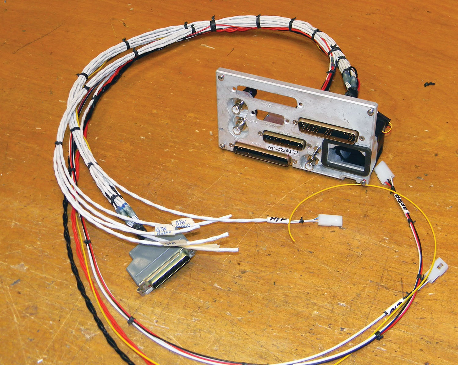
When faced with troubleshooting a homebuilt without diagrams, many avionics shops will charge the owner to create a set. That can be either an easy or miserable task, depending on the complexity of the suite and the quality of the build. It can be even more of a hassle if the existing harnesses aren’t labeled. Be ready to pay the regular hourly shop labor rate for the effort and be turned away at some busy shops that don’t want to deal with it. Wiring diagrams that are valuable for troubleshooting don’t have to be complicated. You can create them by modifying and marking up the interconnect schematics as shown in the installation manual to reflect your install. Your kit is custom, and so is its paperwork.
Since EFIS suites generally have multiple components, or LRUs (line replaceable units), you can even document on the diagram where the component has been installed in the airframe, pointing out areas of access through certain inspection plates, for example. This might ease the disassembly chore when accessing the component and its connectors buried in the airframe. Worth mentioning is that the EAA offers a personal-use version of the SolidWorks industry-standard CAD software free to members. You can make a professional set of prints that really can add value to the kit, or at least make it more attractive for a shop to work on.
Avoid wiring failures in the first place by wiring it like the pros. Have a realistic discussion with yourself about your skill set. If you are new to the world of avionics wiring, consider training to properly strip, crimp and solder connectors, build wiring bundles with proper strain relief and chafe protection, and thoroughly understand ground connections and what they mean for overall performance. The effort will pay back. Whether you are building your own kit or troubleshooting and repairing the avionics in one that someone else built, chances are good that you’ll have your hands in the wiring at some point. Building and maintaining a kit means you are also an avionics tech. See the sidebar below for some suggestions on training and guidance.
Display Failures
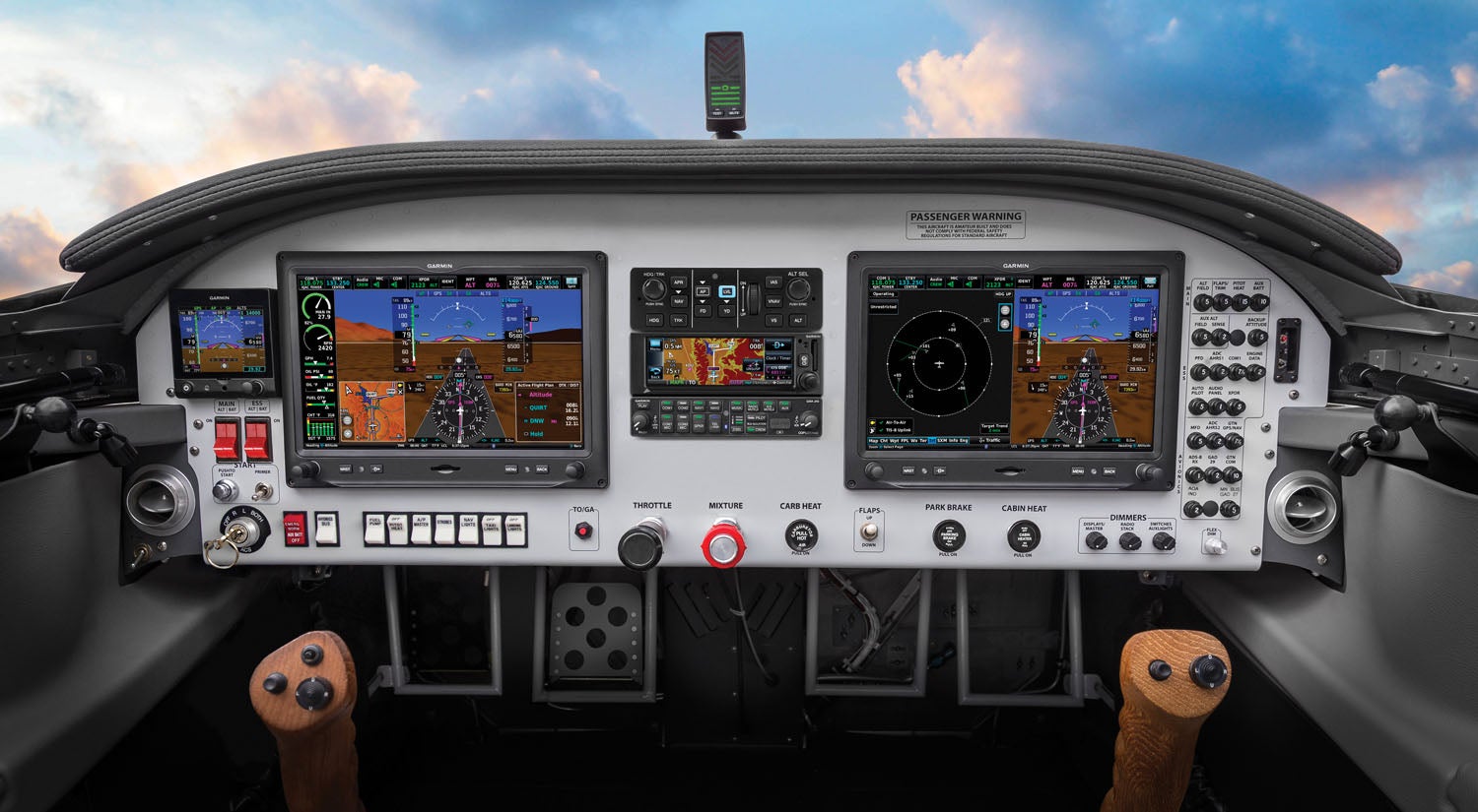
Perhaps the most basic failures to deal with from a troubleshooting standpoint are screen failures. Yes, they do go dark because hardware can fail. While Experimental avionics aren’t TSO’d, and software certification levels aren’t always to the standard of certified equipment, display reliability has gotten a lot better over the years. Unless you’ve done something boneheaded by connecting aircraft voltage to an input that wasn’t intended, the chances of a display failure are rare. In multi-screen suites, there is often redundancy where the secondary screen becomes the primary in the event of a failure.
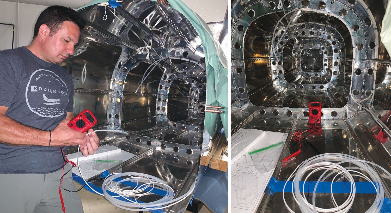
When faced with a dark screen, the first thing is to make sure you aren’t dealing with a charging-system failure. Know ahead of time at which input voltage the display will shut down. In a 14-volt system, it’s often around 11 volts or so before things either shut down or behave wonkily. Some systems will show the precise display input voltage in the setup menu, and you should always monitor bus voltage. Not getting any juice? Access the main connector at the display and measure the input voltage and chassis ground with a multimeter. (Yes, the main and avionics power must be on.) If you don’t have voltage, work backward to the circuit breakers. Breakers do fail, as does the wiring that’s attached to them. If you don’t have push/pull breakers but fuses instead, that’s a more straightforward check.
If there are two identical displays, you should be able to swap connectors to verify the power and ground input. That’ll tell you if it’s a hardware failure, or you might catch an unsecured connector. Sometimes connectors come off (or half off) with vibration. Make it a point to routinely inspect main harness connectors to make sure they are secure.
Heading Issues
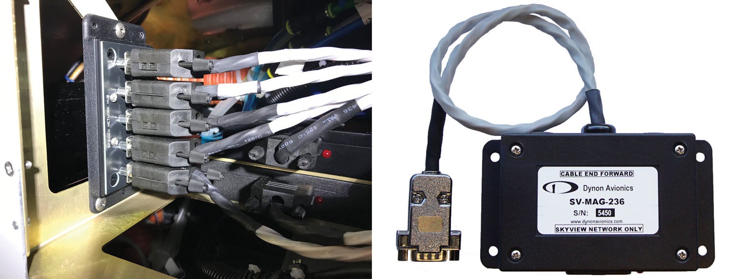
Nothing can be more frustrating than trying to zero out the heading error that might exist with any EFIS. Almost all troubleshooting efforts will be focused on the magnetometer and on the heading calibration setup menus. Troubleshoot heading error, and you’ll quickly have an appreciation for getting the magnetometer installation right the first time while adhering to its installation limitations when putting in other equipment. There’s little room for error.

How the magnetometer is installed in relation to the nose of the aircraft is generally critical, so if you’re battling heading error, make certain that the sensor is mounted exactly as the installation manual specifies, usually lined up with the nose. Even mounted a couple of degrees off center will create an error. Find some piece of aircraft structure that you know lines up with the nose and use that to line up the orientation of the magnetometer. That’s not easy to do when mounting the sensor out in the wingtip, so when troubleshooting, put a sharp eye on the magnetometer’s mounting. Is it secure, or has it shifted? I’ve seen some sensors mounted with only one of four screws—and a few mounted with no screws—but cranked down with tie wraps. That’s certainly not what you want.
Generally speaking, all mounting hardware needs to be non-ferrous materials such as aluminum, plastic or brass. Many stainless-steel screws are alloys with some ferrous material in them. That’s an error already built-in.
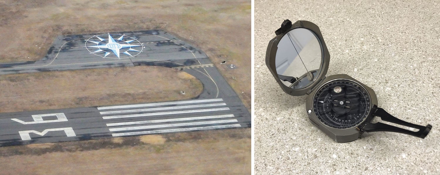
If the hardware is mounted properly, I will start troubleshooting a heading problem with a known-accurate magnetic compass or, better, an accurate sighting compass. If you have a mag compass installed (some kits do not), now is the time to do a mag compass alignment because you can use it to help with the magnetometer alignment procedure. Again, get a second person to come along. You’ll want to find an interference-free area on the airfield to do the calibration (if it can’t be done in flight). Some airports have a designated compass rose, and if not, ask the local maintenance troops where they do their runups and calibrations.
If you can’t find any problems in the wiring and you’ve ruled out interference, there is likely a good level of internal self-diagnostics available. As one of many examples, Garmin’s G3X Touch has a magnetometer interference utility that you might run any time you make changes to wiring and add additional components, especially ones with electrical discharge that come within 10 feet of the magnetometer. When in doubt, you can send screenshots and CSV log files stored on the system SD card to Garmin. These files are also helpful in troubleshooting AHRS and autopilot problems.
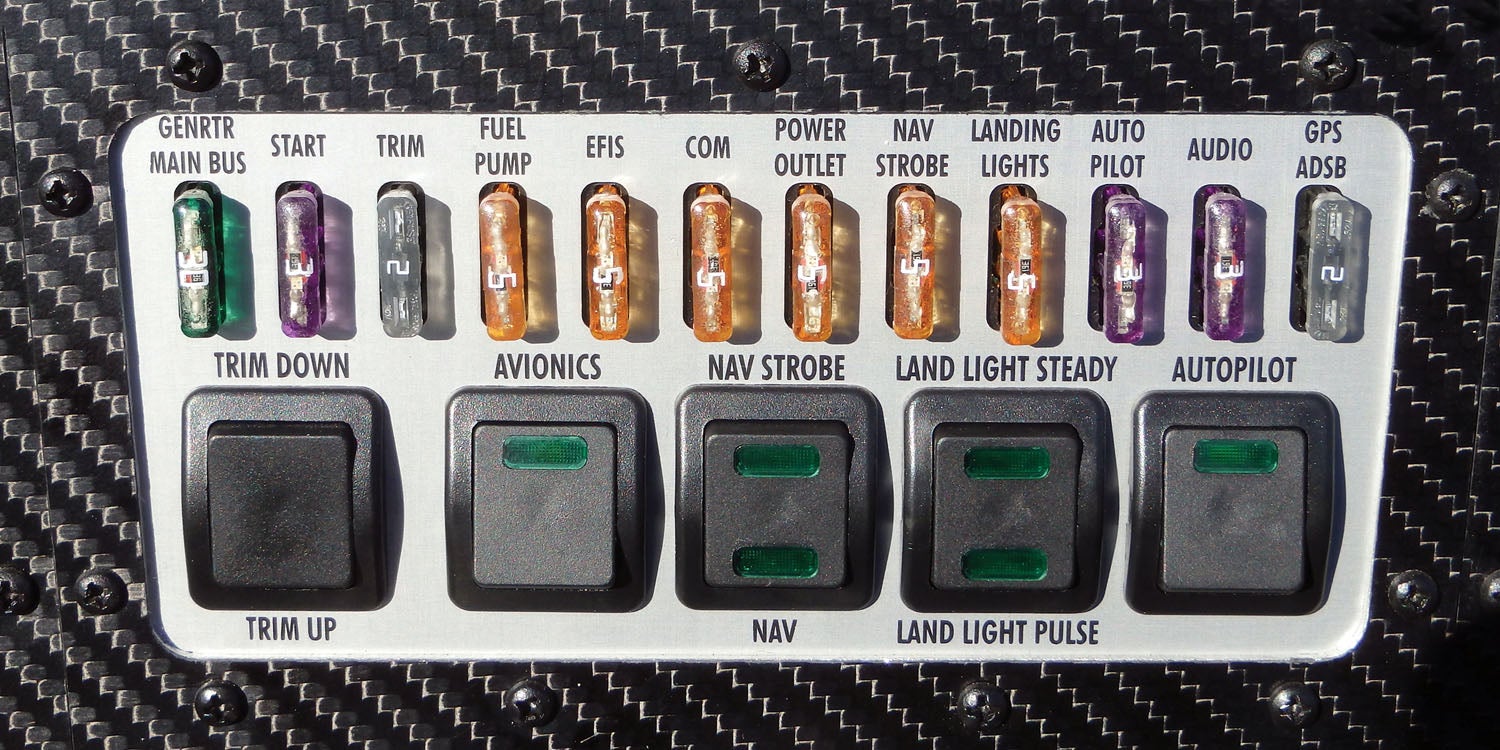
Some EFIS heading systems have a yaw offset. Suppose you can’t line the magnetometer exactly with the nose of the aircraft (some requirements are within 3°), and you know what the discrepancy is. In that case, you can enter the offset value and then proceed with the calibration procedure. At that point, the system knows the starting error when it figures out what north is. Worth mentioning is that most systems can compensate for constant magnetic interference, but they can’t compensate for intermediate magnetic interference—current pulses from strobe lights and the current pull from switching on the pitot heat, as two examples. Remember, current creates magnetic fields. That’s why you’ll want to mount the magnetometer as far away from current paths as possible and avoid localized ground connections in favor of a common ground for the entire aircraft.
As Garmin’s Gepner put it, “We rely on installers to put the magnetometer in a magnetically clean location and then doing a good compass rose swing to set it in the right direction.”
It all comes down to following the manuals, no matter what system you have. That doesn’t always happen. Dynon’s Michael Schofield called it as he’s been seeing it. “Calibration problems with things like magnetic heading, fuel systems and trim systems come down to folks not really being deep readers of the installation manuals, which has always been a challenge for us.”
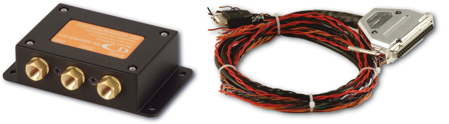
Configuration, AHRS
Sometimes the configuration module (the device wired into the harness or self-contained in the display that stores calibration and configuration settings) may be at fault or wired improperly. Install this in a location that you can easily get to because they can fail. I’ve been called to troubleshoot some systems where the installer forgot to install the configuration module in the harness. That surely won’t fly. And autopilots generally won’t fly if the system senses a fault. Even if you don’t recognize a subtle data failure, the autopilot disconnecting (or failing the start-up sequence) could offer on-the-fly troubleshooting clues if you understand how it’s interconnected.
Sometimes the disposition of digital data ports can offer some clues. For example, on the Dynon HDX, each SkyView display has five general-purpose serial ports, and the status of each serial port is shown with transmit (TX) and receive (RX) character counters and the port’s current baud rate. The character counters show any outgoing or incoming character and roll over at 9999. If there’s data missing, data likely isn’t flowing. Additionally, Dynon SkyView displays provide access to vital information on the Display Hardware Information page. It’s a helpful diagnostic tool.
Follow the configuration procedures closely per the manual and in the proper sequential order. When calibrating the AHRS computer, for example, the system might also require a recalibration of the magnetometer. Talk about a tail chase—your heading was perfect before aligning the attitude, and now it’s invalid because you didn’t do a fresh heading calibration. Before making any changes to anything, make a list of things you need to do as prescribed in the maintenance/install manual and check them off as you do them. Otherwise, you might end up with more “red Xs” than when you started.
Speaking of red-X conditions, attitude and heading failures (especially soft failures) are generally considered no-go items for IFR flying. They can also involve deep troubleshooting, so before you begin, ask some questions that might guide you in the right direction. When you saw the red X, was it only on the heading data portion of the EFIS or was it the roll, pitch or both that was flagged? Suppose the pitch and roll data was red-X. Did the PFD offer any messages like “ADAHARS ALIGNING: KEEP WINGS LEVEL” (that generally means that the system reset) or “ATTITUDE FAIL,” meaning the LRU has no output or there’s a com path failure. Install manuals generally have troubleshooting sections that can help point you in the right direction. Use it.
Stay connected with the aircraft and consider what it was doing in the minutes prior to the failure and what if any error messages did it throw. Was it on the ground during taxi, turning, flying straight and level or climbing? How long did the failure last, and did you also notice a GPS position error or navigator failure? On the G3X Touch, you can go back into the Info page and press the MSG softkey to see the messages again, but only within an hour of the occurrence.
Some problems may be minor but still a nuisance. Maybe you don’t see true airspeed, for example. If the TAS data field on the EFIS is dashed (at sufficient indicated airspeed) or red-X, check the wiring at the temperature probe. If it checks good, try swapping the probe.
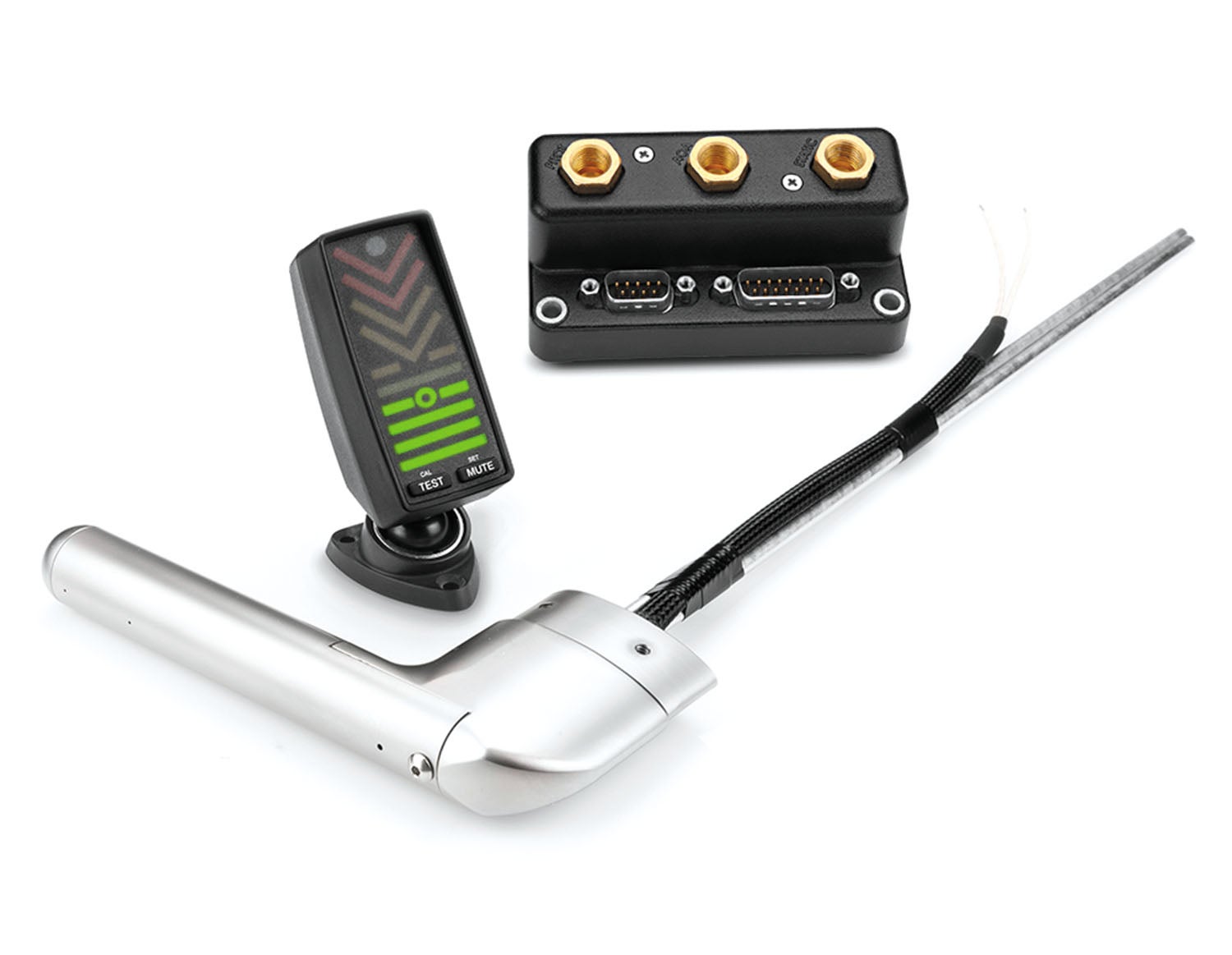
Water intrusion can be a common issue in air-data computer failures, especially when installed downhill of the static lines. When flying in heavy rain, water can run down the pitot and static lines and ultimately work into the electronics—a setup for component corrosion and eventual failure. Speaking of pitot systems, many pitot tubes have integrated angle of attack sensors with dedicated AOA pressure ports. For smooth, constant and accurate AOA data, the pitot probe should be mounted as close to the wing’s leading edge as possible to allow for the best, constant airflow. Mounted farther back will often cause choppy and unreliable readings. Last, when bringing the aircraft to the shop for a pitot/static and transponder inspection, remind the tech that the pitot tube is equipped with an AOA port. I’ve seen some techs damage the differential pressure port by not teeing it off correctly and running the system up to high altitude, while drawing considerable vacuum on the AOA port.
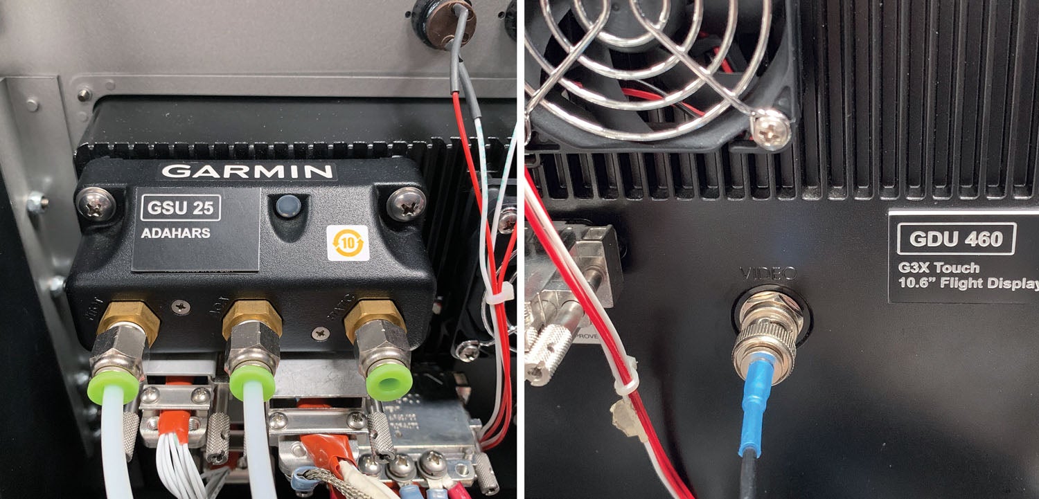
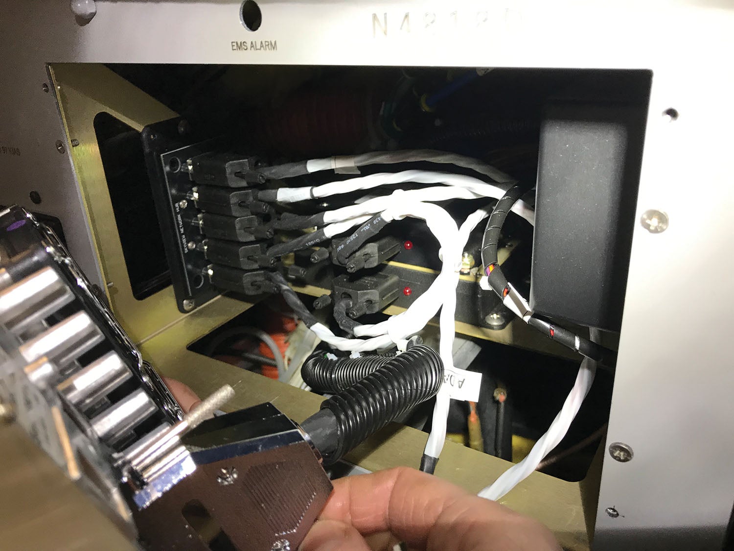
While doing an inspection of the hardware, make certain that the AHRS computer is mounted on a rigid surface, supported by as much structure as possible. Vibration is the enemy, so you want to isolate the computer from engine vibration and subsequent airframe harmonics the best you can. Even a vibrating D-sub connector that isn’t tightened against the chassis can cause grief with the internal gyros and accelerometers. Don’t just hand-tighten connectors that were meant to be firmly secured. Crank ’em down.
If you have dual systems, perhaps a Garmin G3X and a G5, for example, perform the calibration procedure for each at the same time (or during the same aircraft leveling session). Not necessarily simultaneously, but calibrate both systems while the aircraft is leveled since both will be using the same level reference. Even 2° of leveling difference is enough to throw off the calibration. Moreover, if you started with one EFIS and added another, both systems should be freshly calibrated. If not, there could be minor differences in pitch and roll attitude between the two. While you might not see them with your own eyes, the discrepancy could be enough to alter the calculations being performed internally. If the error is significant enough, you might even see an “attitude mis-compare” message on systems that are connected together, as the G5 and G3X often are. A mis-comparison should cause the autopilot to disconnect. And no, electronic attitude displays don’t have parallax adjustments like mechanical attitude gyros do. Set the pitch and roll offset when the aircraft is precisely set for level flight. Don’t eyeball it on what you think is a level ramp. Put it on stands and level it accurately.
Software and Hardware Mods
Finally, if the wiring all checks out, you might very well be dealing with a component failure. Before buying expensive replacement LRUs or sending yours out for flat-rate repair, work closely with a shop experienced with your system. The shop might have test harnesses, although with EFIS hardware it is almost impossible and impractical for most shops to run all of the components together on the bench. Also, work with the manufacturer directly. Your system could have a diagnostic log you can download and provide to the manufacturer’s tech support engineers. They’ll likely ask to see it.
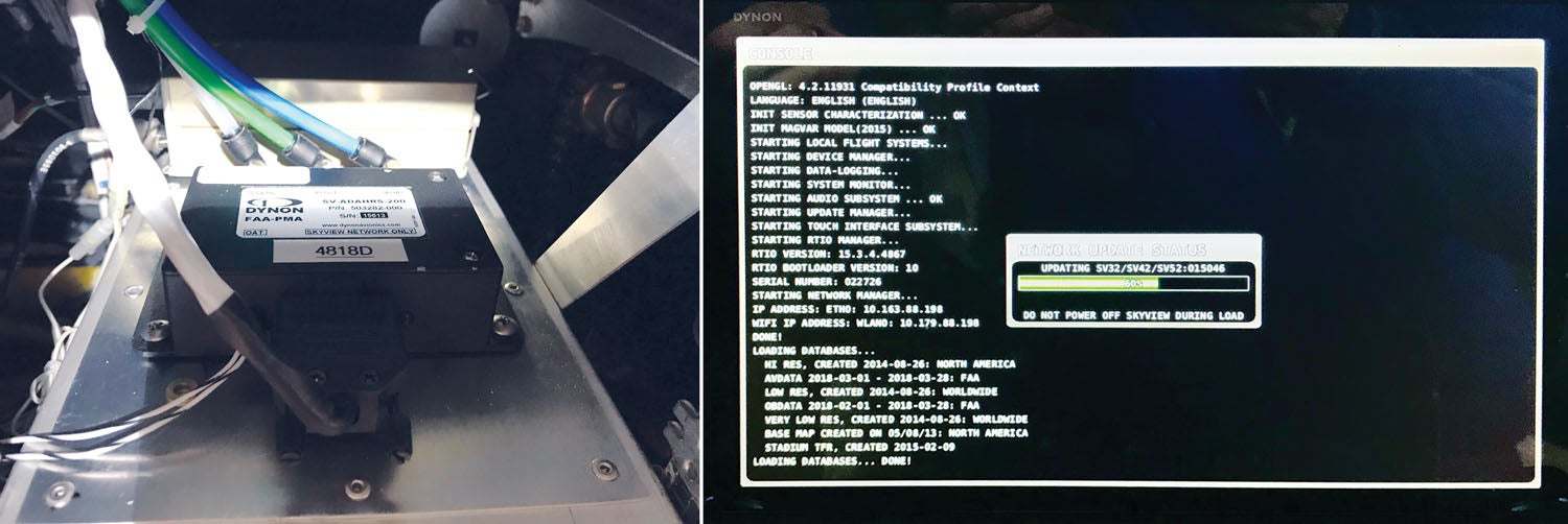
And before yelling for help, be sure the system has the latest operating software for your given interface. The tech will likely require that an update is performed before diving deep into the troubleshooting. Be sure to follow the latest software bulletin when making the update, and if you do the update in the aircraft, connect a power cart or solid external voltage.
While autopilots are an integral and critical (and sometimes terrifying) part of the EFIS interface, it’s worth covering autopilot troubleshooting and tweaks in a separate upcoming article in KITPLANES®. In the meantime, got a problem that you can’t seem to solve? Let’s hear about it.
![[Credit: JetStream Rider]](https://www.kitplanes.com/wp-content/uploads/2026/04/AdobeStock_345999332.jpg?w=218&h=150&crop=1 "2026 Avionics and Lights Buyer’s Guide")
![[Credit: Dynon]](https://www.kitplanes.com/wp-content/uploads/2026/04/EMS-stand-alone_HDX.png?w=218&h=150&crop=1 "Dynon Unveils Scalable Engine Monitoring for Kitbuilders")
![[Credit: Lisa Turner]](https://www.kitplanes.com/wp-content/uploads/2026/02/Fuel-Selector.jpg?w=218&h=150&crop=1 "Fuel Follies")


