We are about to delve into such mysterious things as wavelength, dielectric foreshortening, and the art and science behind baluns and quarter wave sections. I promise to be gentle with the theory and math. I also promise to leave the Greek letters shuttered up in their little houses.
Mostly, I don’t delve deeply into theory and try to make the math as simple as possible (but as Einstein said, no simpler). Those of you who are truly conversant with brothers Faraday and Maxwell may find some of my approximations to be a bit naïve, but for those struggling with Ohm, it may shed some light onto a pretty complex subject.

The antenna end of the balun with the short copper braid strips soldered to the coax braid.
Let me pick an oddball frequency as an example to use throughout this column. I assure you that there is nothing unique or tricky about 113.0 MHz, other than it is splat in the middle of the VOR/LOC band. I could just as easily have used 109.3 or 116.4, but for ease of writing, let me stick with good old 113.0.
So what exactly does 113.0 MHz mean? It means that the energy created at this frequency by a transmitter oscillates (goes back and forth from zero to a positive peak, back through zero to a negative peak, back again to zero) 113 million times in one second. That’s a lot of back and forth motion, isn’t it?
If that transmitter is connected to an antenna, that energy is launched into the air (or into space if you are out beyond the earth’s atmosphere) where it continues its little dance 113 million times a second. But it is traveling at the speed of light, which as we all know is pretty fast. How fast? About 186,000 miles per second. If you multiply it out (a mile is 5280 feet times 12 inches per foot), you find that light travels 11,784,960,000 inches a second. OK, so we have a wave vibrating 113 million times a second (113,000,000), so it seems reasonable to ask how long one of those vibrations travels in one second. The answer is speed divided by frequency, or just a little over 104 inches. That’s not quite three yards, which is about how much the Chargers made per carry on the ground last football season. But I digress.
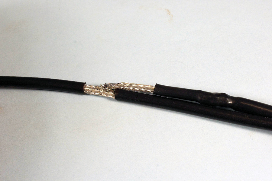
The two braids soldered together at the bottom end of the balun. A wire of any length you choose may also be soldered at this point for static drain and lightning protection.
So wow, the little wave we launched from our antenna is going very fast and vibrating very fast, but we have a number for how many inches it goes in one vibration. We’ve got a special name for that “number of inches,” and we call it one length of a wave, or more commonly, one wavelength. We can divide that number by 2 and call it a half wavelength, or by 4 and call it a quarter wavelength.
Some might say that a lot of the stuff I write is not quite moving that fast, and some would go so far as to say it’s moving only half-fast, i.e., “That is the most half-fast drivel I’ve read in a while.” (Forgive me, editor, I couldn’t help myself.)
The wave slows itself down when it has to travel through a substance other than a vacuum or air. It is sort of like running through air and then trying to run through water. The water slows you down, and although radio waves can travel through plastic, they are slowed down by what is called “velocity factor” in coaxial cable with plastic insulation between center conductor and the outer shell or shield. In the most common of the cables with solid plastic between center conductor and outer shell or shield (such as RG-58 or RG-174), the polyethylene plastic (called the “dielectric”) has a velocity factor of 0.66. That means that instead of 11,784,960,000 inches per second, the wave only travels 0.66 of this speed, or 7,778,073,600 inches per second. If we translate that into wavelength by the equation above, we find that a wavelength in coax cable is about 69 inches. A half wave is then 34 inches, and a quarter wave is 17 inches.
So what? All I’ve done so far is to bore you with a lot of arithmetic that has no practical application. Or have I?
It turns out that quarter waves are real special animals in electronics. If you will permit me a little hand-waving at the chalkboard, let me just state something really magic. If I have a quarter wave piece of coax cable and short the far end, the near end appears open. If I have the same quarter wave of coax and let the far end be open, the near end appears to be shorted. That truly appears to be some sort of sleight of hand or powdered bat wings and newt toes, but it is the truth. Give me a double-wide chalkboard and Maxwell’s equations, and I can prove it to you. But for now, accept it as gospel. With a quarter wave, a short at one end is an open at the other and vice versa.
A balun can be made out of plain old 50-ohm coaxial cable. The author prefers RG-58 because it is easy to work with and readily available.
For this next bit of the article, you need to know that there are two common kinds of antennas in the aviation world—ground-referenced and balanced. A ground-referenced antenna uses a large sheet of metal (like a fuselage) or some fingers of metal somewhat perpendicular to the antenna itself. A com antenna on a metal fuselage or a transponder “spike” antenna on a pie plate are good examples of this type of antenna. And, since the “radiating element” is vertical with respect to the earth’s surface (except, perhaps, in a lomcevak), we say that the antenna is “vertically polarized.” The little waves are dancing up and down relative to the hunk of metal that simulates the earth’s surface (hence the term “ground” plane antenna). This kind of antenna may be fed directly with coax cable—nothing else is required.
The other kind of antenna is balanced—that is, it has no ground plane, but instead uses two elements that are equal and opposite one another, like the “rabbit ears” that we use for a VOR/LOC antenna. This sort of antenna cannot be simply fed with coax, but instead needs some device that converts the BALanced antenna to the UNbalanced coaxial cable. Get it? BAL to UN, or balun. Now we get to do our quarter-wave trickery.
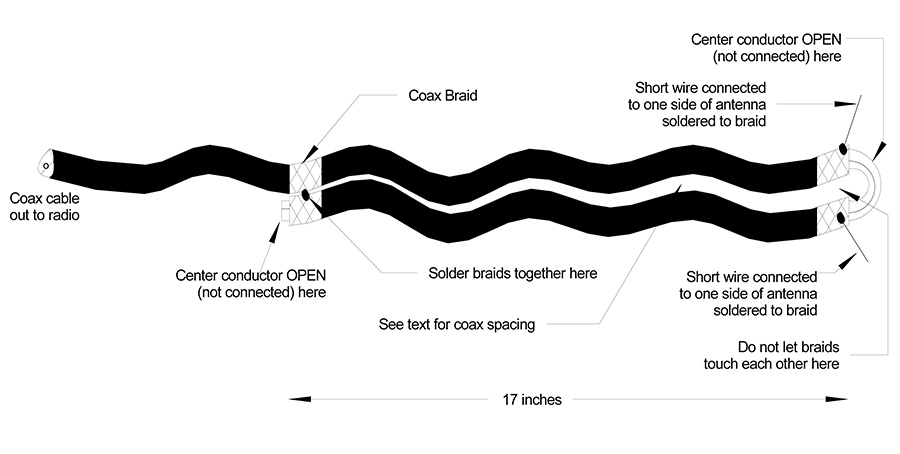
The balun is made out of plain old 50-ohm coaxial cable. I prefer RG-58, as it is easier to work with and can be purchased almost anywhere—even The Shack if absolutely necessary. At the antenna end, the outer black plastic jacket is stripped off for about an inch or so, and the braid is split and cut back to expose the center conductor insulator. Seventeen inches (quarter wave in coax, remember?) back down the coax, the outer plastic jacket is stripped from both the coaxes and soldered together. Please note that nowhere at the antenna end is the center conductor connected. Why? Because if you recall, an open in the quarter-wave coax at one end (where the braids are soldered together) is a short at the other end. Hence, the energy from the center conductor is transferred to the braid at the antenna end and the power has gone down a quarter wave, been reflected at the open end, and come back another quarter wave to be connected to the antenna.
What that means is that if one side of the antenna is “pushing,” the other side (half wave = 180°) is “pulling” and vice versa. Thus the antenna is not only fed in a balanced manner, it is fed so that the elements are in push-pull with one another. Pretty nifty for a nickel’s worth of coax.
The spacing between the two coax lines is really non-critical, so long as at the antenna end you really make sure that the braids do not touch one another or the whole balun is worthless.
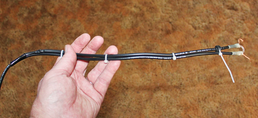
The whole balun assembled.
Please note that the center conductor of the coax is not attached anywhere at the antenna end. The antenna elements are attached to the shield (or braid) of the coax at the “top” end of the balun only, one element to each side of the shield. Just for completeness, where the two braids are soldered together 17 inches back down the coax towards the radio, if you connect this solder joint to the airframe with a wire (no matter how long), you have effectively grounded the whole antenna for lightning protection.
Once again, necessity is a mother. Along with the com ground plane we did in the May issue, I needed a “test” antenna for the VOR/LOC band. And, since the VOR/LOC signals are transmitted with horizontal “polarization,” the receive antenna on the new RST Skunk Works needed to be horizontal so that the little dancing horizontal waves from the VOR transmitter will find a good home in the horizontally polarized shop antenna.
Quickly, I wanted to show you that rigid wooden rods are not necessary to support the copper tape I use everywhere I can for antennas. In this case, we simply pushed the copper tape down inside the PVC plastic water pipe “ears.” And how long do we make antenna elements? Quarter-wave in air, of course, and we already did that calculation. The theoretical is 26 inches but for some esoteric reason (called end effect), we always throw in a 5% foreshortening factor, so the antenna elements are actually 24.7 inches. I generally round down and make them 24 inches and that always seems to be about right.
Not only that, but the elements don’t have to be straight. Since all the signals I wanted to hear were due west of my little hilltop, I bent the elements to increase the gain of the antenna in the direction I wanted to receive.
Don’t believe that coax is the only way to make a balun. You can also use little donuts of sintered powdered iron called “ferrite” that will effectively do the same job, but at the cost of a lump of ferrite near the antenna. Either way, you will get a good antenna. Most metal ships use coax, plastic airplanes use ferrite as a general rule.
What’s on the burner for future columns? Back when I had dark hair, I did an article about a backyard wind vane that had lights and such (KITPLANES® July, August, September 2005) made from plastic water pipe. I did one some years before that made from thin, pine wall paneling. The “Pietenpol” pine did what wood exposed to the elements will inevitably do and rotted out. The “VariEze” plastic pipe is still there, but the batteries have pooped out and getting the thing apart is almost impossible. So, I guess the only thing left to do is make an “RV” out of aluminum and such, and make it mechanic-friendly for repair. Or how about a headset tester? More coming. Stay tuned.


s")


