This is the last chapter of a way to make a serious power supply for your mobile device…Android, iThing, or something else. They all want 5 volts regulated at something between half an amp and 2-and-a-half amps. Why 5 volts? That standard is lost into digital history, but so long as it is the standard, we’re going to have to meet it.
This article alone ought to let you save enough money to extend your KITPLANES subscription into the next decade. Apparently there is an outfit out there that will sell you a 5-volt multi-ampere power supply for your airplane for only $350. How about we do something for the same power supply for less than $10 a channel? They have two channels for $350. We have two channels for $20. Do the math.
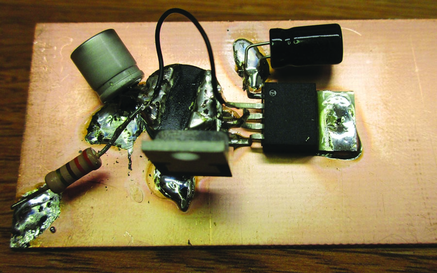
The entire 5-volt converter consists of only these five components. If it were to go into production, I’d want to add an output Zener to blow the fuse/breaker should the circuit overvoltage, and a Z-bead and bypass capacitor on both the input and output wires just to be absolutely sure that there wasn’t any digital “trash” being radiated.
We had some trouble last month with heat when we tried to get a single linear supply for much more than an amp a channel, much less getting a double supply for 3 amps a channel. With a switching supply, heat is not a problem in the least. Even for those of you with 24-volt aircraft, you won’t have much trouble getting rid of the switcher IC heat.
There has been a bit of chatter on the homebuilt newsgroups about switching supplies driving some avionics up the wall with noise. Yup. Buy it off eBay and you take your chances (not particularly good chances, by the way) that your device from some Far-Eastern company could give a good care about how much noise their cheap device generates.
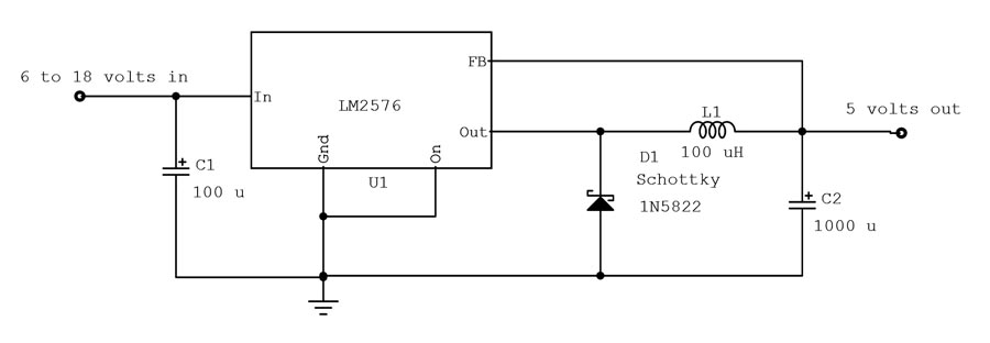
Total parts cost of this engineering model circuit was less than $3 (plus postage and handling). Critical items are D1 that must be a 3-amp Schottky diode, and C1 that must be very close to pin 1 of the integrated circuit U1.
So, here we go with a very efficient, well regulated, well designed, and quiet 5-volt 3-amp supply with no heat problems (24-volt aircraft, you may have to do some field testing to keep the heat down. Twelve-volt aircraft, no problem at all.) I used about 3 square inches of scrap PC-board material, and it ran just barely warm to the touch after an hour’s operation.
Another problem we had with our linear supplies was getting them spot on 5 volts with a variable control. Five-volt switchers are available with laser-trimmed ICs that will get you within a couple of percent of 5 volts and is extremely stable over time and temperature.
So, what is this magic device? No magic at all. The folks over at Texas Instruments have been perfecting integrated circuits since Jack Kilby shared the Nobel Prize with Robert Noyce of National Semiconductor in 1958 for inventing it. This is just a refinement of Jack and Robert’s work after 50 years of research and refinement.

The ultimate test for “birdies” or digital trash is to put the converter right next to the antenna of a scanner and listen across the entire aircraft band.
The device? A simple switching regulator. Here is a brief description of how it works: You have a large voltage. You want to change it to a smaller voltage but don’t want to lose a lot of power in the transfer. Simple (only until you start to do the IC design itself). Take the input, turn on a transistor to output voltage, and turn it off when the voltage reaches the voltage you want. Wait a bit, and when the voltage starts to fall, turn it on again, off again, on again…
What have we achieved? If we turn the transistor on hard, we have a lot of current through the transistor but practically no voltage. Ohm told us that the transistor will be passing a lot of current by no voltage. What is the wattage dissipated? Lots of current times zero voltage. Current times voltage is zero. No power dissipated. When the transistor is open, lots of voltage crosses it with zero current. Current times voltage is zero. No power dissipated.
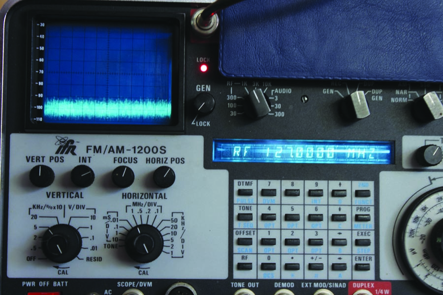
Another excellent test for very low-level birdies is to connect the input of a spectrum analyzer that can see down into the sub-microvolt level onto every lead on the converter and then let the spectrum analyzer (the blue-green screen in the upper-left corner) scan across the entire aircraft band. This is the scan from 122 to 132 MHz, and it looked the same from 108 to 137 MHz.
Now, nothing is perfect. There will always be some residual current and voltage to produce a power loss. These switching power supplies are roughly 90% efficient. That is, if you want to produce 5 volts at 2 amps, you will be sucking 10 watts from the 12-volt supply. If 10% of that is turned into heat, you have 1 watt of loss—hardly the 20 or so watts from last month’s linear supplies.
But the noise, Jim, the noise? Noise is produced by sharp spikes (“sparks”) in the conversion process, which is the result of turning transistors on hard and off hard, as we said in the prior discussion. The art is to turn the device on just hard enough to get efficiency and just soft enough to keep spikes from forming. Somehow our colleagues in the Far East are using devices (much cheaper to produce) that don’t have that soft turn-on and turn-off.

This is the switched level at the full 3-amp output. Note the rounded corners on the square wave. This is the secret to keeping noise out of the converter extremely low. Sharp, square corners make high-frequency noise. Rounded corners do not.
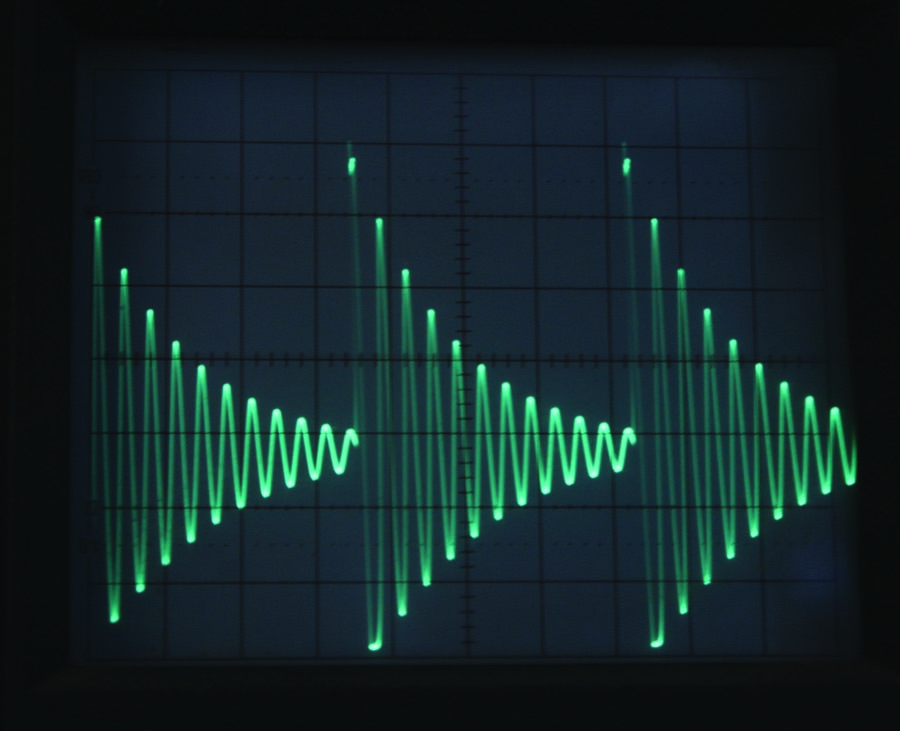
This is the same switched level at zero output current. Note again that these are nice and rounded corners that smoothly transistion into the rounded square wave as we start to draw current.
The schematic and the photos show a 3-amp, 5-volt regulator from a 12-volt aircraft supply. What is very significant is the images of the spectrum analyzer showing absolutely no spikes in the aircraft band and no increase in the noise level of the spectrum analyzer. The final test is to put the power supply on the top of the scanner and let it search the aircraft band. Not a bit of noise on any frequency.
I’m a belt-and-suspenders sort of guy if it doesn’t cost much in money or weight. For less than a nickel, I’m going to put a “Z-bead” and a disc ceramic capacitor on each input and output. And I’m going to put the board inside of a metal enclosure.
The LM2576-5 switching regulator is, hands down, the slickest IC I’ve ever had to deal with. I tried everything I could do to make it act up, and nothing seems to bother it. I messed with the inductor value, ran both the input and output capacitor values up and down, and used half a dozen different “catch diodes” for D1 to no effect. I will say this: If this is your first homebrew electronic project, you will not be disappointed or frustrated. The little rascal is bulletproof. The only thing I do caution you on is that the catch diode needs to be a Schottky device with a current rating to match the output current you expect to draw from the circuit.
I think we’ve about exhausted the voltage regulator thing. How about next time we climb back up into the VHF nav band to find a new way to split nav signals and split a glideslope signal off for free?
Then we may get into the LED nav light controversy and a few other things. Until then…stay tuned…

![]()
Jim Weiris the chief avioniker at RST Engineering. He answers avionics questions in the Internet newsgroup www.pilotsofamerica.com-Maintenance. His technical advisor, Cyndi Weir, got her Masters degree in English and Journalism and keeps Jim on the straight and narrow. Check out their web site atwww.rstengineering.com/kitplanesfor previous articles and supplements.


