Several of my airport neighbors have fancy electric tugs to haul their planes about. So far, I have gotten by with my homemade, bent out of 3/4-inch conduit tow bar just fine. But as the years (mine) accumulate, and the airport authority has repaved the hangers and taxiway with greater slope for drainage, thoughts of having a tug have been brewing in the back of my mind. Turns out they are fairly expensive to buy, and that kind of money I would rather put toward the next plane enhancement or upkeep.
With some research and a bit of work (actually, quite a chunk), I found that most of the key elements to build an electric tug are reasonably available. After a quick estimate of necessary materials and costs, the project was off to the races!
To cut to the chase, my tug came in at about $400, but that was using a few surplus items I had on hand. If you need to buy every last piece, the cost will be in the $450 to $500 range. As they say, your results may vary.
Finally, a key goal was to make this project within reach of the average (but handy) builder—no welding, no moon rock parts, but still a high-performance, full-featured tug. With that in mind, let’s get started!
Design Features and Approach
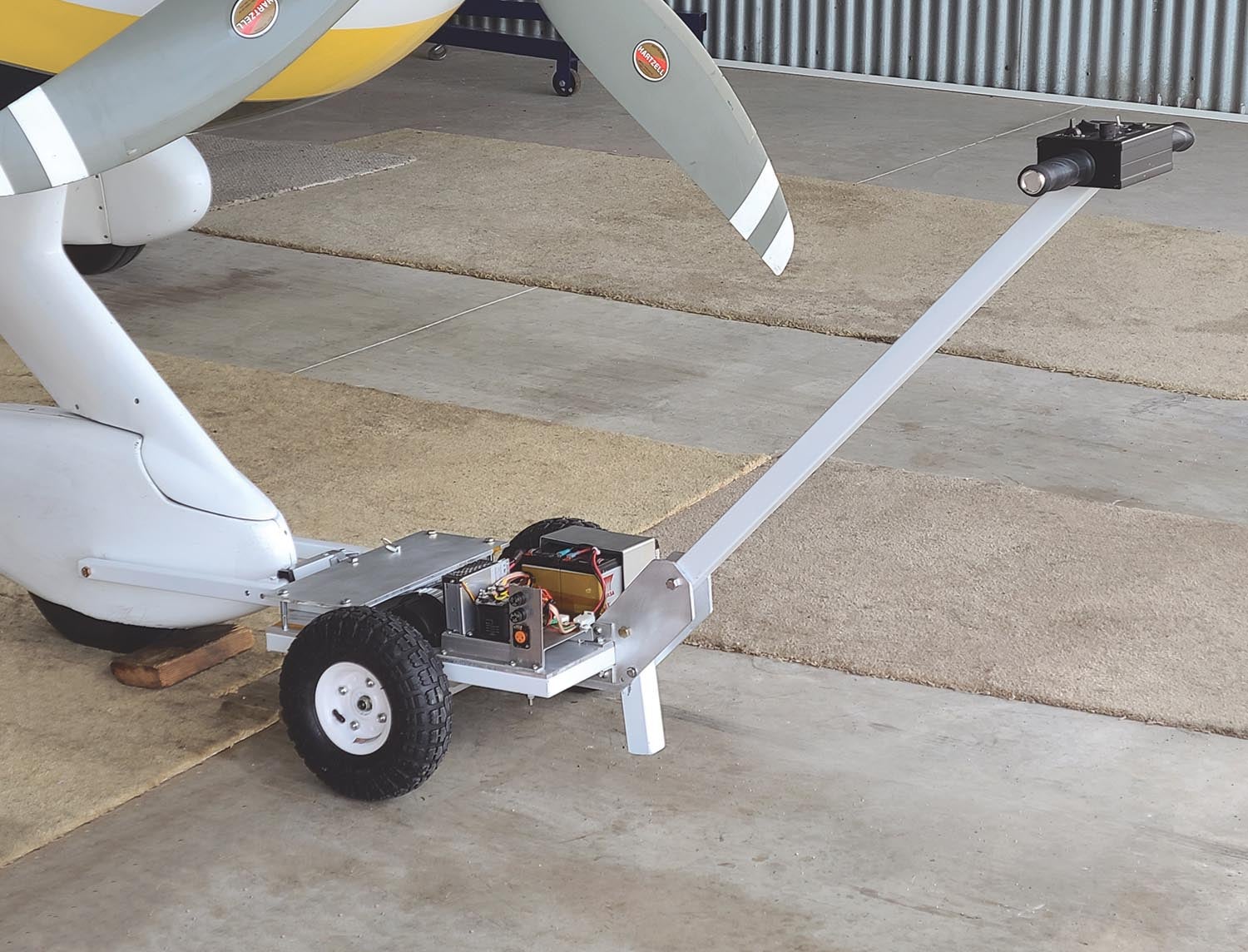
The first key decision is what kind of tug? Electric was assumed, but beyond that there are two basic approaches. Either include a ramp to lift and carry the nose (or tail) wheel and gear, or have arms that engage and pull/push on the wheel. Most gear is already set up for the latter kind of attachment, so that is the approach I chose, not to mention it is easier to just attach the arms than to shove a platform under the wheel and lift. The only downside to this design is that it takes a bit more learning to use. It’s sort of like driving a shopping cart backward when pushing the plane, but you get used to it.
Beyond this fundamental decision, the plan was for a comprehensive set of features.
- Live axle with a differential for ease of steering.
- Powerful variable speed electric drive.
- No sprockets and chains.
- Commonly available gel cell or AGM batteries with decent capacity.
- Servo/linear actuator arm control to engage the nose (or tail) wheel/gear.
- Pivoting or optionally locked arm assembly to suit the user’s style of steering.
- Complete and easy-to-use set of controls and displays.
That seems like a lot of expensive stuff, but it turns out that live axle electric drive assemblies, including a differential, are available and inexpensive on eBay for the electric cart/chair/scooter market. That is a key enabler. And surprisingly, pulse width modulation (PWM) motor controllers good for 100 amps are also not expensive these days.
Batteries are the next biggest expense but can also be had for $60 to $100 or so. Wheels are cheap at Harbor Freight. The rest is bits and pieces, although in quantity they do add up! Finally, the steel used is mostly simple hardware store material, and the only other significant variable is the aluminum base plate, whose cost will depend on your individual scrap pile or may be significant if you must resort to McMaster, Aircraft Spruce or a metal supply house.
Mechanical Design and Construction
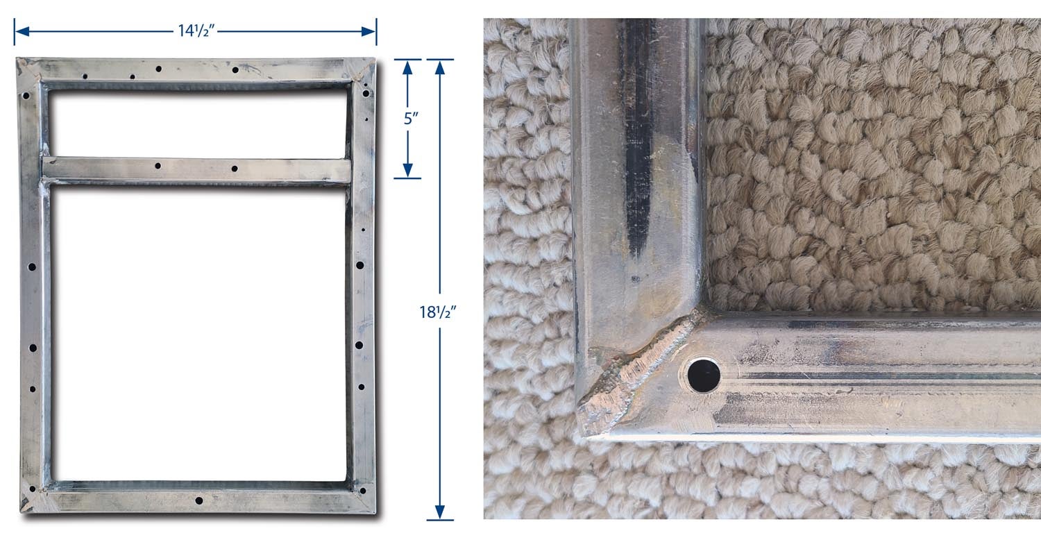
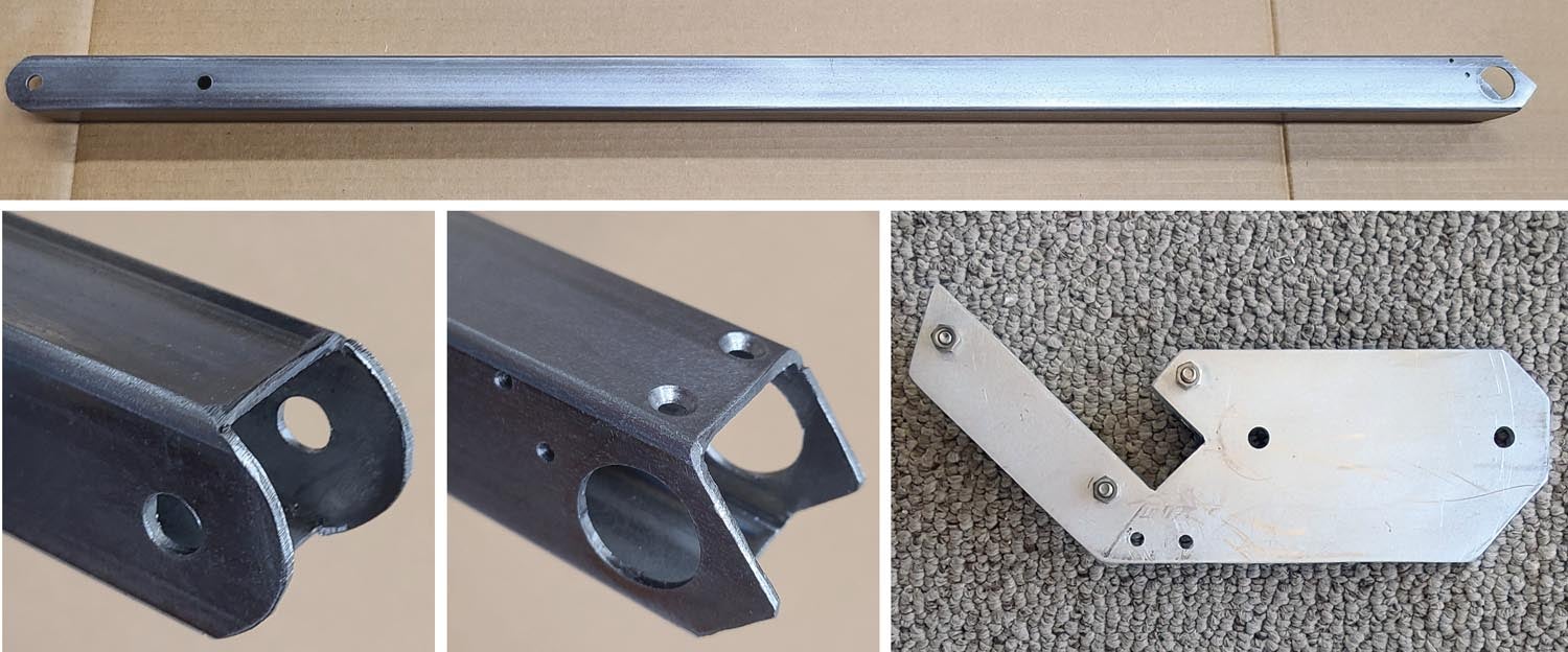
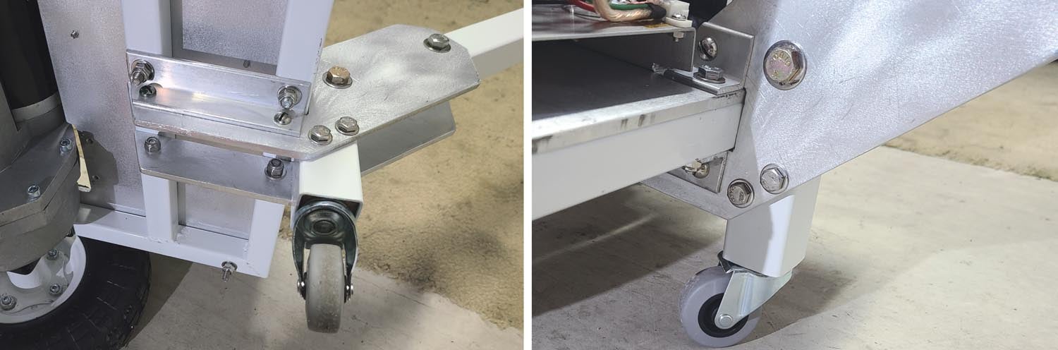
The steel frame is made from 1-inch square steel tubing, which is formed into a rectangle with 45° corner cuts and is brazed along the top, bottom and inner corner seams. The brazing is ground down somewhat flat on top to accommodate the aluminum base plate. This approach was chosen to avoid the need for welding and can be accomplished with a brazing torch. Toward the handle end, the base steel frame has an additional cross member for strength to help absorb forces pushing down on the T-handle (leveraging against the attachment to the plane) to increase tire traction when needed.
Now let’s talk wheels. First, if you are using the recommended drive unit, it comes with 7/8-inch Woodruff key slotted axles and 1/2-inch NF threaded ends, which is very nice. But readily available inexpensive wheels, such as those in the parts list from Harbor Freight, have bearings and are meant to freewheel on a fixed axle. One approach is to make your own hubs with ⅞-inch centers to convert them. Another is to buy more expensive wheels for a live axle, but you will still likely need to make some kind of adaptation.
The approach I took here, and I encourage your creativity to choose your own perhaps better way, is to remove the wheel bearings from the inexpensive wheels (just tap them out) and make an adapter to go from the (typical) 1.5-inch hub inner diameter to the 7/8-inch keyed axle. This was accomplished with a cut piece of 1.5-inch O.D., 1-inch I.D. aircraft tubing and a piece of 7/8-inch to 1-inch keyway adapter, available from the go-kart world.
OK, here I cheated and welded those into the wheel hub, but you can also drill and pin as an alternative. This adaptation requires disassembly of the wheels and installation of the spacers in the portion of the hub that once housed the bearings. Since these were not originally meant to be driven wheels, I found it useful to mount the tire on the inner side of the hubs with a bit of adhesive (silicone rubber works well) on the rubber where it sits against the inner and outer hubs to keep the tire from slipping under load and shifting the inner tube. Silicone rubber will be easy enough to peel in case an inner tube needs to be replaced. Once done, the wheels go onto the axles with 3/16-inch Woodruff keys.
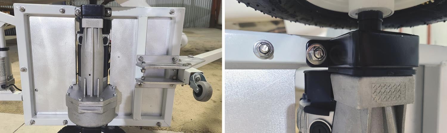
The arms to engage the airplane are also made of 1-inch square steel tubing. You will want to adapt the length as needed for your plane. Looking from the top of the tug toward the arms, I chose the right one as fixed and the left one to pivot. The ends of the arms mount hardware for your particular method of engaging the plane. In my case, it is simply a pair of bolts with the correct diameter to engage a pair of holes in the front gear fork. This is an area where you will need to do a custom job.
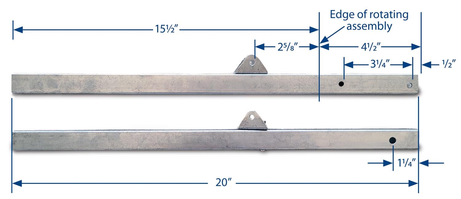
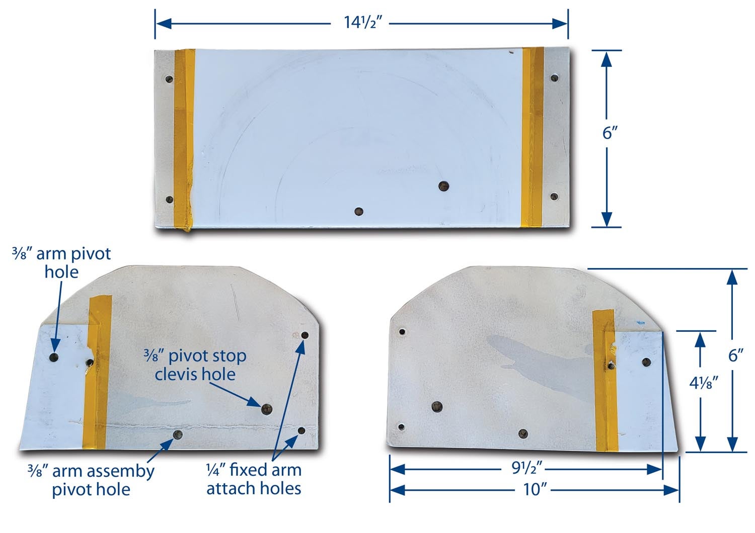
The plate that covers the rotating arm assembly as well as the main tug base plate have 1/32-inch polyethylene pieces taped on to smooth the arm assembly’s rotation. All these plastic pieces will also be held in place by several holes that will go through them. The plate is mounted with four corner bolts and spacers. The spacers will need to be measured and ground to a length that tightens the assembly just enough to remove any slop but still allows reasonably easy rotation.
Once the top plate is made, it and the rotating assembly need to be positioned carefully on the centerline and at the front edge of the base plate and clamped. Then drill the ⅜-inch hole for the pivot point of the arm assembly and the second hole for the pin to fix the rotating assembly when desired. These holes should be made with a drill press to assure perpendicularity.
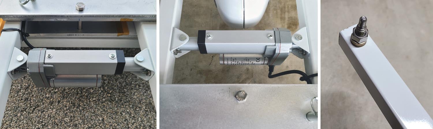
The rotating left arm is moved by a linear actuator. You will need to fabricate a pair of mounting brackets to attach the actuator, which in my case were from the same square steel tubing. Choose a location that clears the airplane (such as the nosewheel pant) as close to the tug as possible yet avoids a collision of the actuator with the frame at the expected greatest rotation of the arm assembly. My experience has been that about 20° of rotation in either direction is more than enough to accommodate the tightest turn I pull my plane through.
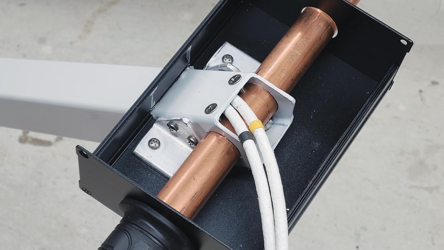
The next part of the project is the tug handle. It consists of a 1.5-inch square steel tube attached at the base to a pair of aluminum plates that transfer forces to the base. Two bolts secure the tube, while removal of the upper bolt allows pivoting the handle for unit storage in less floor space if so desired. Another short piece of 1.5-inch steel tubing is also attached to the aluminum plates and acts as a foot when the tug is not attached to the airplane. Its height is also subject to your own best fit. Note the alternative foot arrangement featuring a wheel, which I added later. The upper end of the handle uses a piece of 3/4-inch copper plumbing pipe as the T portion. Its convenience will become apparent later when we discuss the electrical design and throttle choice. Fabricate the mounting plates at the base from 1/4-inch aluminum and attach as shown with short pieces of 1×1-inch aluminum angle.
At the top, the aluminum box that houses the controls is attached with another pair of 1×1-inch angles. The box needs a rectangular hole cut out for the steel tube to pass through. With some care in progressive cutting, filing and trial fitting, this can be made to be neat and tight. Holes in the box end plates match the copper pipe, and a pair of screws secure the pipe to the steel tube.
You will likely take things apart and reassemble for various building operations. The last disassembly will be to paint the steel components. Clean them thoroughly before painting. I chose white. Lastly, as you do the final assembly of the pivoting arm assembly, clean all surfaces thoroughly to remove any remaining metal chips that would otherwise impede smooth operation and chew up the surfaces.
Electrical Design and Construction
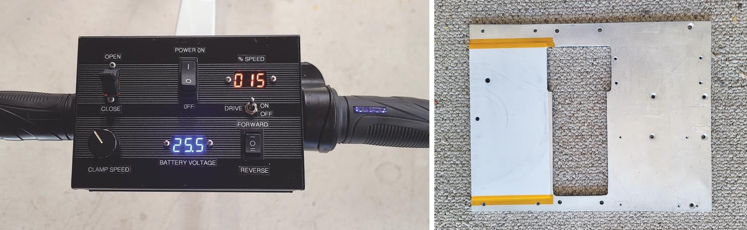
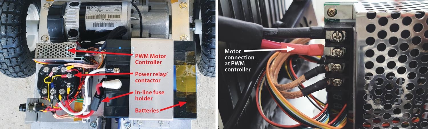
The tug’s wiring diagram is at www.kitplanes.com/electric-tug. There are numerous ways you can adapt the design if desired. The main function is motor speed and direction control. In this design, speed control is implemented with a 100-amp PWM motor controller, which conveniently enough comes with a direction control switch, on/off switch and percent power LED readout. The PWM module is mounted on the electrical platform, along with the primary power contactor, two fuses and the charging jack. I used a power relay I had lying around, but a 24-volt contactor/solenoid is a good, economical alternative.
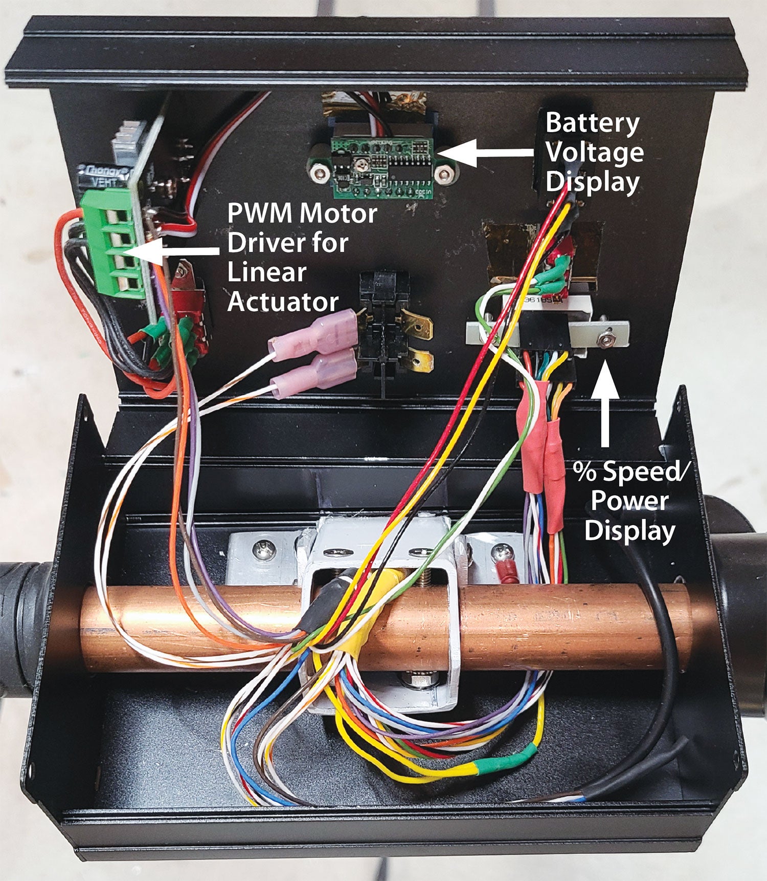
A small 2-inch-stroke linear actuator operates the left arm and is driven by a lower power PWM controller, located up in the handle control box. This controller comes with a potentiometer, which gets mounted in the control box. It also has a double-throw direction control switch, which I replaced with a spring-loaded momentary DPDT mom-off-mom bat-handle switch to run the actuator and arm out and in. Note that the specified actuator is a 12-volt unit, which is OK with the 24-volt system given that the controller is used pretty much at half power or less for reasonable operating speeds.
I used a pair of 12-volt, 18-amp-hour AGM cells and included an automotive high-current fuse holder in series with their connection to the contactor. A 60-amp fuse has worked well for my operation. Connect the batteries in series at one end with a wire or drilled aluminum strap. It’s advisable to provide some insulation/protection for the series tie strap as well as the + and – 24-volt terminals. Connect the negative side of the batteries to a common ground, typically the aluminum top plate. You will also need a 24-volt battery charger. These often come with a three-pin DIN connector for the output, so that is what I wired as my charging port.
Connect the contactor power output side and system ground to the input of the motor PWM controller per the polarities indicated. This is important to get right, as a reversal will damage the controller. Connect the motor leads to the controller output terminals. Terminal lugs that are sufficiently large to accommodate the motor wire may require you to trim the sides of the lugs to fit the PWM controller terminal strip.
The motor PWM controller includes a potentiometer with an on/off switch, a percent-power three-digit LED indicator and a center-off reversing switch. Here’s where things get a bit tricky: These are on short wires connected to the controller and need to be located up in the handle control box. Other wires that need to go up to the control box are primary 24-volt power and ground to energize the contactor, secondary power for the linear actuator, two wires to the linear actuator, plus an LED voltage display to monitor battery charge. All in all, this amounts to 25 wires. In my case, I ran two 15-conductor cables up the handle and terminated them at the base with a DB25 connector to allow the handle to be removed if necessary.
Here are a few other things to keep in mind while wiring. It turns out that the wires from the PWM controller can be clipped off their switches and display and are long enough to be directly soldered into the DB25 connector.
The linear actuator PWM module with its potentiometer is mounted directly to the top of the control box. Its direction switch gets cut off and the wires instead soldered to the bat-handle switch.
The controller output leads and power input leads will need to be soldered to the back of the controller instead of using the provided terminals because of clearance issues if you use the specified control box.
The last trick in wiring is that I wanted the throttle/speed control to be a rotating right-side handle grip, like a motorcycle, electric scooter or bike. Once again, luck prevailed! In the electric scooter and bike world, this kind of twist grip control is common and readily available on eBay, including the left-side fixed grip. And they are universally 7/8-inch I.D., which is why the 3/4-inch copper pipe, which is 7/8-inch O.D., works so well as the T-handle core.
Finally, these twist grips all use Hall effect devices that put out 0 to 5 volts on three wires. Luckily, this is directly compatible as a replacement for the potentiometer on the PWM controller. So simply cut the potentiometer off and splice three wires in the handle: red to red, black to black and green (typically) to the potentiometer center wire.
There are quite a few components mounted to the box top cover. Take care to anticipate potential interference with center-mounted items and the steel and copper tubes. Also, as you wire from the base components up to the box controls, keep careful track of which wires are which. Before applying power, use a meter to verify the correctness of the wires end to end.
Assembly, Test and Operation
Once all the wiring and mechanical assembly are complete, ensure that the main power switch and motor controller on/off switch are off, and set the motor direction switch to center off. Attach the batteries and turn on the main power switch. The battery voltage LEDs should show somewhere in the range of 25.5 volts +/- for fully charged batteries. Turn the motor controller switch on with the direction switch still in the center position. The percent speed should show a low value and go up to around 90% when you rotate the throttle.
Next, try the linear actuator in both directions at various speeds. I found about half speed to be good. Reverse the actuator wires if needed to correspond correctly to the in/out switch markings.
Now it’s time to run the motor. Some caution is advised here, as the motor is powerful and at full speed with no airplane attached, the unit will go quite fast. This turns out to be rather useful when moving the tug around without the plane attached, but be careful—my first run in the basement included one of the arms putting a hole in a door!
Turn on the motor power, switch to forward and see which direction it goes. You may need to reverse the motor wires or the direction switch. Carefully advance the throttle and see how the unit works, then try it in reverse.
Now it’s time to test the tug with the plane. I found it easy to engage the wheel with the right arm by positioning the tug at a slight angle from the left and then turning left to engage the wheel. Then, gingerly toggle the left arm in with the actuator, nudging the tug just slightly as the left arm aligns and engages. If your engagement mechanism includes some chamfers, most of the time the arm will snap right in.
From here, it is a matter of building experience with directional control. With the arm assembly locked, you will need to hop the tug a bit for directional control in pushing mode. With the arm assembly pivoting, pulling is easy, but you will need to learn what actions result in what directions when pushing the plane. I find it easiest to allow the arms to pivot when pulling the plane out and leaving them fixed for pushing it back into the hangar. At times you will also need to press down on the T-handle to increase traction and avoid wheel slippage. Each time after using the tug, I check the unloaded battery voltage (give it a moment after running) and charge if it has dropped to about 24 volts. I found a charge to last for quite a few uses with the pair of 18-Ah batteries.
Parts Commentary
If 1/4-inch aluminum is too hard to find or expensive, 3/16-inch should be sufficient. However, you may wish to use a thicker walled version of the 1-inch square frame tubing. If you are not close to a Harbor Freight store, they offer the same wheels online.
The link to eBay for the drive axle requires some explanation. There are usually a couple of very similar drive axles listed, including the one I used. But check what you order for the right width and similar power: 24-volt is mandatory and typical, but there may be some with lesser power. While they may indicate “only one (or two) left,” they seem to keep reappearing. The worst case is that factory-new drive axles are easy to find at www.alibaba.com for about $200 but require shipping from China.
Finally, for inclement weather I decided to add an optional cover. It consists of a piece of smoked acrylic 14.5 inches wide, with a pair of 0.060-inch-thick pieces of aluminum for the sides. Look on YouTube for videos that describe the simple acrylic sheet benders you can make with a couple of pieces of wood, a piece of nichrome wire and a power supply—neat stuff! Enjoy your new toy!
Download additional drawings and photos.
Control Wires
| Function | Color | Cable | D Shell Pin |
|---|---|---|---|
| Direction Switch BLK | BLK | 1 | 1 |
| Direction Switch YEL | YEL | 1 | 2 |
| Direction Switch RED | RED | 1 | 3 |
| Speed Pot BLK | WHT/BLK | 1 | 4 |
| Speed Pot YEL | WHT/YEL | 1 | 5 |
| Speed Pot RED | WHT/RED | 1 | 6 |
| Linac – | PURPLE | 1 | 7 |
| Linac + | GREY | 1 | 8 |
| Contactor coil | WHT/OR | 1 | 9 |
| Speed Pot Switch BLK | WHT | 1 | 10 |
| Secondary +24 from fuse | OR | 1 | 11 |
| Ground | BRN | 1 | 12 |
| Primary +24 from fuse | WHT/BR | 1 | 13 |
| Display 6 pin side RED | RED | 2 | 14 |
| Display 6 pin side BLK | BLK | 2 | 15 |
| Display 6 pin side GRN | GRN | 2 | 16 |
| Display 6 pin side WHT | WHT | 2 | 17 |
| Display 6 pin side YEL | YEL | 2 | 18 |
| Display 6 pin side OR | OR | 2 | 19 |
| Display 5 pin side RED | WHT/RED | 2 | 20 |
| Display 5 pin side BLK | BLU | 2 | 21 |
| Display 5 pin side GRN | WHT/BLK | 2 | 22 |
| Display 5 pin side WHT | PURPLE | 2 | 23 |
| Display 5 pin side YEL | GREY | 2 | 24 |
| Speed Pot Switch RED | GRN | 1 | 25 |


Old electric wheel chairs have most of the components to build the tug. Often these can be had for free or very little cost. You can find these on Craigslist or Facebook.
This is a really outstanding design. It’s now on the list for days when waiting for more airplane parts to come in!
I have the same problem with my hangar. I like the design!
Harbor freight sells a plug-in 110 volt winch for around $130.00. Hook it to the tail tie down to “get over the hump”. Seems to work ok for me.
Allen and Gregory,
Thanks for your comments! The readily available 24V drive axles, integrating the motor with a differential, were a key enabler for the project. And as mentioned and referenced in the detailed parts list, these are also easily found, new or in good used condition on eBay. And this thing works so well, I have fun with it every time I haul my plane out and back in!
I have a project in the works using an Electric Wheelchair as note by Allen. The advantage mainly is that all of the controller, charging, etc. is already done, and the wheelchair is designed to go over uneven ground. All I have left at this point is the pickup for the wheel. The wheelchairs in general are designed to move about 300 lbs. When you get rid of the chair components you are left with about 150 lbs. in the unit with the batteries. So overkill for the hangar but if you are moving it elsewhere a good thing to consider. With a bit of tinkering it should be possible to ride the chair while moving the aircraft too.
Really like this idea Paul. I’ve never had a close look at an electric chair. Any pics of how it’s modified?
Excellent info. Thank you.
can’t find the wiring diagram
Click the “Download additional drawings and photos.” just above the Parts List.
Great article. I love the detail and parts list with links. I found a transaxle with wheels so will save a bit. I had already planned to do a drill powered snowblower axle and have been wrestling with wheels for that. I got the transaxle for what I would spend on the wheels/hubs/adaptersso will proceed with your design first. I’ve got multiple planes to move so may complete the other and have a tug-off competition.
Greg, Thanks for your kind comments! Enjoy the process and the results!
Hello Reinhard,
I have started acquiring parts to duplicate your tug project. Can you share exactly the multi strand wire specs – gauge – and source – is this hvac wire or aircraft tefzel wire? I cannot wait to get this built – love the idea. Phil Poynter RV9A
Phillip, Overall you need 30 conductors of about 22 or 24Ga, nothing special. I used two 15 conductor cables I had lying around, and that works out better than if you actually had something with 30 conductors, as it might be too fat. Here’s what looks like a perfectly usable 15 conductor on Amazon:
https://www.amazon.com/KWANGIL-22AWG-Conductor-Cable-UL2464/dp/B0CSD5285C/ref=sr_1_1_sspa?crid=20PKOAX8M8U8T&dib=eyJ2IjoiMSJ9.6-Mm27es3TSh0xBX_octEonPVbyopbnRZwg6uhsFu3FE2t_PBsF9NF_zDvy6vxK4v0CiuwQpIxNomHZ__PZZ-MZ-ugJ-XRn4pWHfVwDJ3u2loguRQw9SVanQ_luYjIxBKNL5pSeCnm2-XPJZ9qbrn5MXXz-VmXGeDsvqKN1x__Ydsi07d9zsZkzeZ30QOca2PRZRy5zCV9mZFAAv-j-vVRgj_XelHiYGWPH7aIFJ2dhkL8aORsGkacjgBSNNt6woFWN1ge6z0MdfCIz48qlYfBsaQcbQzDKoGENQdaYR7sA.Ni8GZyWOtyjCnLz-CwmT-xb_HJQWWWrYIp04mBeN5aQ&dib_tag=se&keywords=15+conductor+cable&qid=1715985352&sprefix=15+conductor+%2Caps%2C174&sr=8-1-spons&sp_csd=d2lkZ2V0TmFtZT1zcF9hdGY&psc=1
Good luck, have fun!
Hi Reinhard. I am making your design. Thankyou. How do you stop from over voltage on the linear actuator that is 12V….if you wind the pot full won’t you get 24 volts and burn it up? Is there a way to prevent this? Thanks again.
Hi Glen. Good point. In actuality, you won’t damage the actuator if you were to crank the potentiometer up full for a short time, like by accident. I run mine with the potentiometer at half way, or lower, which is perfectly fine for the actuator. At the time of writing the article, I could not find an economical 12V version of this actuator. Ironically, that actuator is no longer available, but a 12V version is!
https://www.amazon.com/Silver-Linear-Actuator-Stroke-Output/dp/B07BK4FR19/ref=sr_1_4?crid=2G39KU40FE5BW&dib=eyJ2IjoiMSJ9.z2Qyd_6fHPSwKdm6MVav8y0Q5KPZByOvzmLZtE2TkxjjvcycmpRWKt_MD0MtZcvFEtpeY6L5-L-tv_93Z6igwLQPjXI7NgnWVMrFafgAuBXmMeUg_cWVLbcckHQYB3HJw6oHbG4IYEVmS3kpKk7DrD0WhNzDNsDGymM1uOr-yaD1Swg3BkrsoA7osm5GhSOor5TzGAzOwU-Y7zE535rvqK6SU2rxROdC5q12t9vKD1-iDSrsZfDrwe7Njzts3Lb6az0yXXIdBcMVFd9f8vA_oQz-JeA24jFFLntp34Ytn4E.WMQiPDcGQw5bNUAPDaz7hX8i4NqB_eKK0_1ZBBRHXUU&dib_tag=se&keywords=2%22+stroke+linear+actuator&qid=1716673341&s=industrial&sprefix=2+stroke+linear+actuator%2Cindustrial%2C107&sr=1-4
Sorry, I said that backwards! The link is also for a 12V, but it is at least available. The 24V version is:
https://www.amazon.com/Stroke-Actuator-22-5lbs%EF%BC%88100N%EF%BC%89Maximum-Mounting-Brackets/dp/B082F79GWN/ref=sr_1_2_sspa?crid=2HK72QA6FKVNL&dib=eyJ2IjoiMSJ9.xXHlg6LmnvlUDQA9_0DO4pthcoU9AxEJPREtMgvdE54mmusxkO_I_54KTnjO_TjFpRU-ljJfuZfdQnTPtasTGKH99jb7DlmqNse6Cq0bC7M2PpKZui4Wf_ZPT3XIahAmMeKkyI2nkwz5Zd1smYx0NnAt46weeqfmflmGSkNqjNgM5RkPhLandNEcxrEIz1vfuaiKe0nyHLawUAYlC62LFyfAWWIB3hgCAO0W4_qAhSPf4iq7TZXWi2iOqS36JPDDnsNWbL-VYWDbeQ0IPakVN6sZAWBJRB_VqcPzLvZu95w.1H7fpSrrwCk0XEewHY5nPDbBvQV6qC9_Joctt3rJIyM&dib_tag=se&keywords=2%22%2Bstroke%2B24V%2Blinear%2Bactuator&qid=1716673580&s=industrial&sprefix=2%2Bstroke%2B24v%2Blinear%2Bactuator%2Cindustrial%2C119&sr=1-2-spons&sp_csd=d2lkZ2V0TmFtZT1zcF9hdGY&th=1
Thanks again. Do I need 900N to hold the arms closed? Or I could use a 24 to 12 volt step down? I’m not that electronic savvy sorry so just trying to get the right stuff. I have ordered most parts from your list. I found a really nice black 2” linear actuator that is 3000N (overkill but looks solid ) but it says 3.5 to 5 amps so the pwm controller you list might not do that? If it’s only opening and closing unloaded then it won’t draw a lot of amps I guess. Hey thanks again for your time.
Glenn, It takes virtually no force to hold the arms closed. The only force required is the process of moving the arms and engaging them. Once engaged, the actuator will not be driven backwards – the worm gear setup inside will resist pretty much any force – the arms simply stay in place. And the force to move and engage the arms is minimal.
As I’m collecting parts I decided to model the tug in SolidWorks for a several reasons. I wasn’t sure my transaxle was the same size. I needed long reach arms to get to the tailwheel of my Rearwin. It’s well forward of the rudder post. I needed drawings for a friend’s plasma cutter to carve up some steel sheet I acquired. But mostly because I’m a geek and it’s fun. So since I had the drawings, I thought I’d investigate SendCutSend.com. If you need to buy the material anyway, it’s worth a look. I could get the base plate, pivot cover and 2 handle brackets cut from 0.105 steel for ~$120 including shipping. 1/4″ aluminum was ~$215. Check it out.
Would you be willing to share those files?
Hello Reinhard. I’m in the process of putting together an example of your design. I’m at the point of fabricating the attachment arms and rotating plates, but I’m not clear on what hardware to use to secure the arms. Did you use some sort of countersunk hardware, or just flush pins to secure the fixed and rotating arms? It took me a while to realize normal bolts and nuts interfere with the rotating function of the steering plates. What was your solution to adequately secure the arms to the plates?
Hi Reinhard.
Hey the instructions talk of a 100 amp controller but the list of parts states a 60 amp controller. I got the 60 amp should I go 50 amp inline fuse or 60 amp like in the write up. Sorry for all the questions. I have most parts now so keen to start building this.
Not sure why the parts list says 60 amps, it was updated as far as I know. The 60 amp will work but I have had them fail. The 100 amp is more reliable. This is the one I used:
https://www.amazon.com/gp/product/B0B5MMQKJY/ref=ppx_yo_dt_b_search_asin_title?ie=UTF8&psc=1
Reinhard
David,
Yes, in the rotating assembly, there are countersunk 1/4” flat head screws where needed to not interfere with rotation. I should have made that more clear.
What kind of charger would you recommend for these batteries. I assume from the XLR connecter, you are using a wheelchair charger?
Yes, and there are plenty of these available, for example:
https://www.amazon.com/Connector-Lakematic-Technologies-Shoprider-24BC5000TF-1/dp/B08JLR8S8K/ref=sr_1_1_sspa?crid=CSVUB6LPXYAO&dib=eyJ2IjoiMSJ9.aXBjbr7NL1wgeY9bufz-iAyD5ZnN-NWioFN5tP78PYrgRnZ9GDDb3LUchWFt1N55o4tt3KSOhymDjITNx2fI2Pok5eHOCkkpQclKuqhibP3ehzzhIGuH5K2_flOZtX4XGQHSPrj5rMVj7WqUersQQV-gIsaUvavOHVnoGycS7XDoYvQpYaqhgPotHaFBnQAdciS5_GWCxQ2zXrGxviaXnSDCsC1l4z11QKZQZCkVua65b4KtmybpxOjq98CnV2oQMwWf7hjhESrIjHagz-VMIchLyM3BEcvuVcIt6fYtK9s.F3WwAxtnQeLBd-NVmPlhDd_W11Mbj-Bftwc8jgBWq54&dib_tag=se&keywords=24v+5a+3+pin+male+xlr+connector+battery+charger&qid=1722297415&sprefix=24V+charger+with+xlr%2Caps%2C143&sr=8-1-spons&sp_csd=d2lkZ2V0TmFtZT1zcF9hdGY&psc=1
Do you have any additional pictures of your hub/axle adaptation? Based on the pictures I do see, I wasn’t quite following the comment about inverting the hub mount.
The motor/transaxle unit I bought on Amazon has a 20 mm keyed shaft. The HF 10″ wheels have a bore of 1-3/8″. To make the wheels with a keyed 20 mm hub, I used a metric QD bushing from Grainger. Item# 5YLG1 has a tapered 1-3/8″ OD with a 20 mm keyed bore and 1″ overall length. I had to rotary file off one wheel half ID to match the other wheel half bore ID and then I trimmed the long wheel half bore flush with the wheel perimeter on my bandsaw. This way with the QD bushing installed on the inside of the wheel, a large washer under the transaxle nut pulled the QD bushing down tight onto the shaft. The tube stem is on the inside but that is minor considering how easy the QD bushing turns the HF wheels into drive wheels.
Will this tug work for a heavier airplane such a Cherokee six? The only axles that I can locate at the moment are 350 watt / 24 volts, so they appear to be a bit less powerful than what is listed. Will those have a enough power?
what is the mechanical arm for on drive unit you recommended? Should I remove it?
Thanks
Greetings Reinhardt,
I have constructed the tug from a recycled handicap scooter (the controller unit was shot). I used the components mentioned in your article to wire up a new controller unit. However, the motor has two large power supply wires and two smaller “electromagnetic” brake wires. Do you have suggestions on how much “power” to supply across the brake wires to release the brake unit? My unit does slowly move but suggest – I suspect because the electro brake is inhibiting movement. Help please. Thanks Phil Poynter
Should have read “I suspect” rather than suggest – sorry!
Should have read “sluggish” – sorry
I removed the innards of the brake assembly to keep it from interfering.
Comments are closed.