Last month we had a brief general talk about antennas. Let’s get a little more specific about what we need to do to get a decent antenna.
Absent GPS and ADF, all antennas on an aircraft are either ground plane or dipole. A ground plane antenna has a single element situated 90 degrees above an infinite conductive surface in all directions. A dipole antenna has two co-linear elements (pencil-straight) far from any conductive surface. That’s the theory.
Either the ground plane or the dipole antenna elements can be made from any conductor, usually a metal. The best metals (in order) are silver, copper, gold, aluminum, zinc, nickel, brass, and bronze. To tell you the truth, the difference between an antenna made of silver and one made of bronze is so minute that it would take sensitive instruments to tell the difference. On an airplane, you really couldn’t tell the difference. Use whatever metal works best for you.

Now to the practicality. The ground plane on an airplane cannot be made over an infinite surface. We generally restrict “infinite surfaces” to antennas that are constructed on the surface of the Earth (the original “ground” of Marconi’s “ground plane” and still used for broadcast radio and the like). Even an aluminum airplane is not “infinite,” but it works like it to a first approximation. This usually works to our advantage.
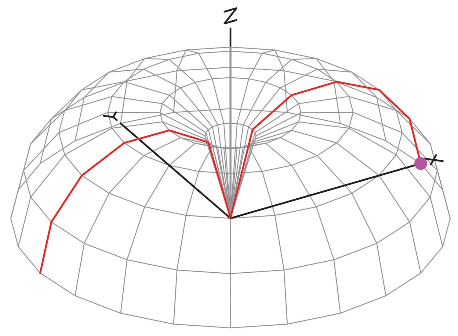
A real “ground plane” antenna has zero radiation below the ground plane; all of the radiation is out and up, away from the ground. Think of a donut dropped over the vertical element from the top. That would make it extremely difficult to talk to a ground station from an airplane as all the transmitted signal would be going up into space (except directly up—the “hole in the donut” effect). However, the ground plane on the aircraft is not perfect, and if you consider the shape of the fuselage, you will see that quite a bit of it points out and down. Thus, an antenna using the fuselage as the ground plane will have a great deal of radiation to the sides and down, which is what we want.
The dipole, on the other hand, wants nothing to do with a metal surface. Its signal is broadside to the dipole, and a vertical dipole radiates maximum signal at the horizon. Think of a donut slipped over one of the elements and moved down to cover the center of the dipole; there’d be maximum radiation at right angles to the dipole, but a huge hole directly off the end of either element.
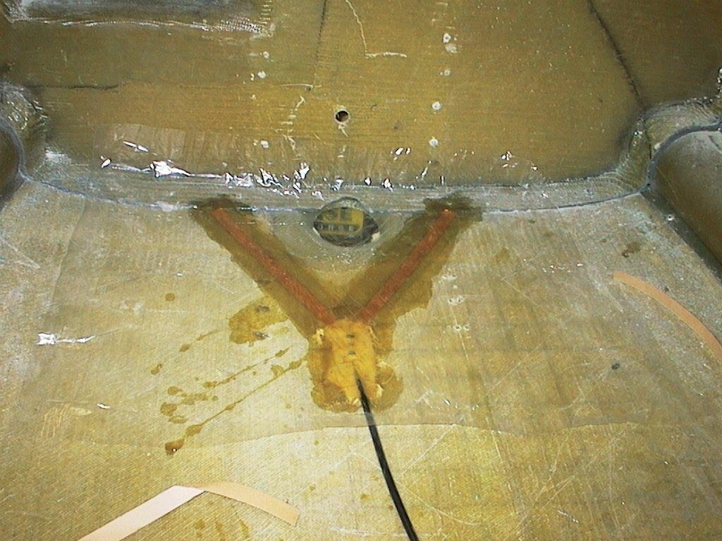
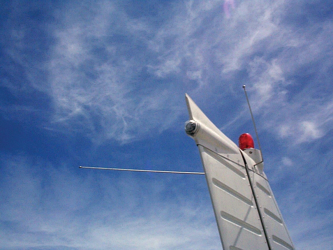
Dipoles are also sort of “numb” at the center to metal. The tips are really quite sensitive to conductors, but at the center you can get away with mounting them on or through a metal surface. It is also true that you can get rid of that “hole in the donut” effect by not aligning the elements straight across but bending them a bit (say, up to an angle of 30 degrees) off each element from horizontal. This makes them look like a very shallow V, with the best reception in the open end of the V. That’s why the “rabbit ears” on a horizontal VOR/LOC antenna on the vertical stabilizer of a lot of metal aircraft point forward to get best reception from where you are going, not where you have been.
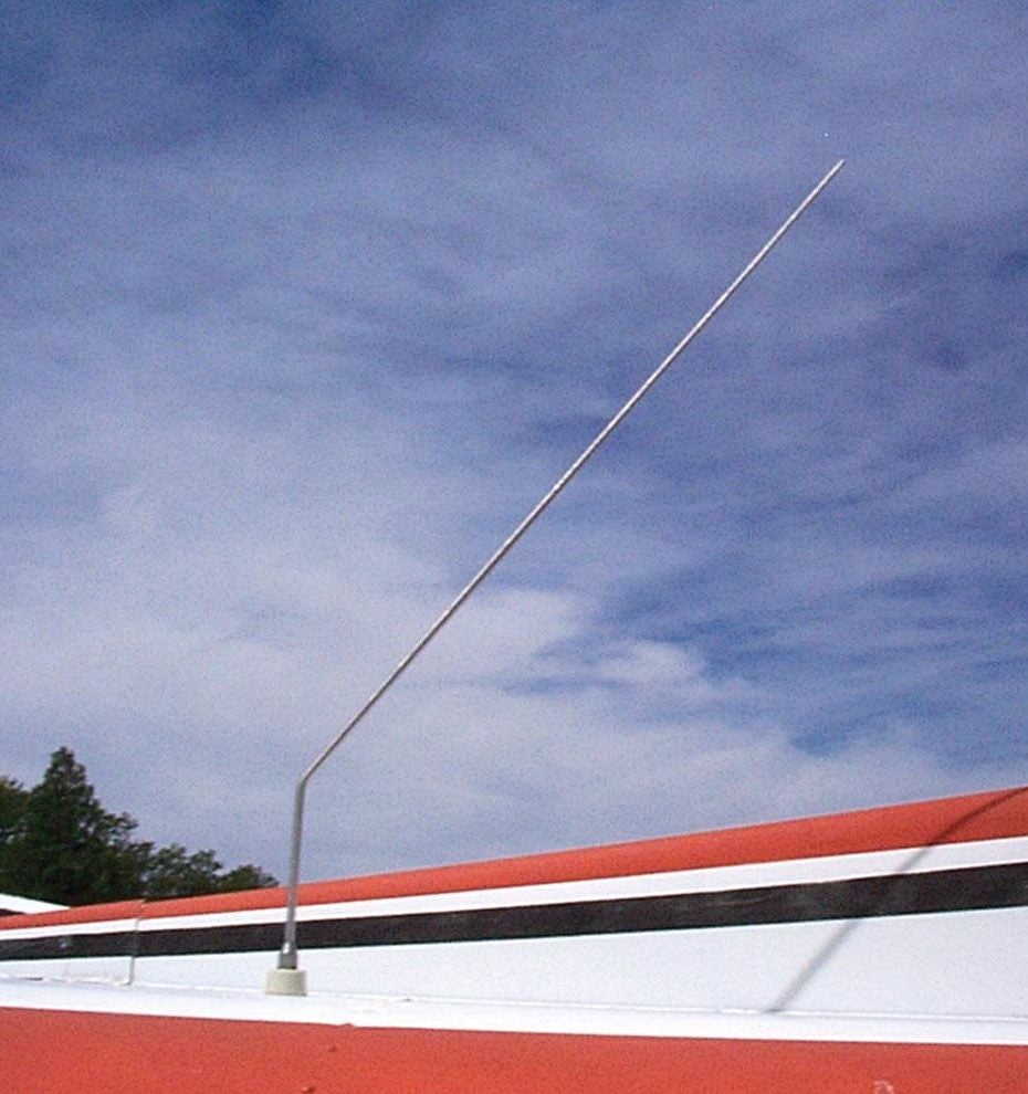
Both ground planes and dipoles have a pretty loose requirement to be “straight.” That is, especially on a plastic airplane, you can bend the elements around to conform to the shape of the airframe, so long as in general the elements stay either vertical or horizontal—especially in the last 25% of the element length.
One thing that the dipole requires that the ground plane does not is a balun (pronounced BAAH-luhn; more about that in a future column).
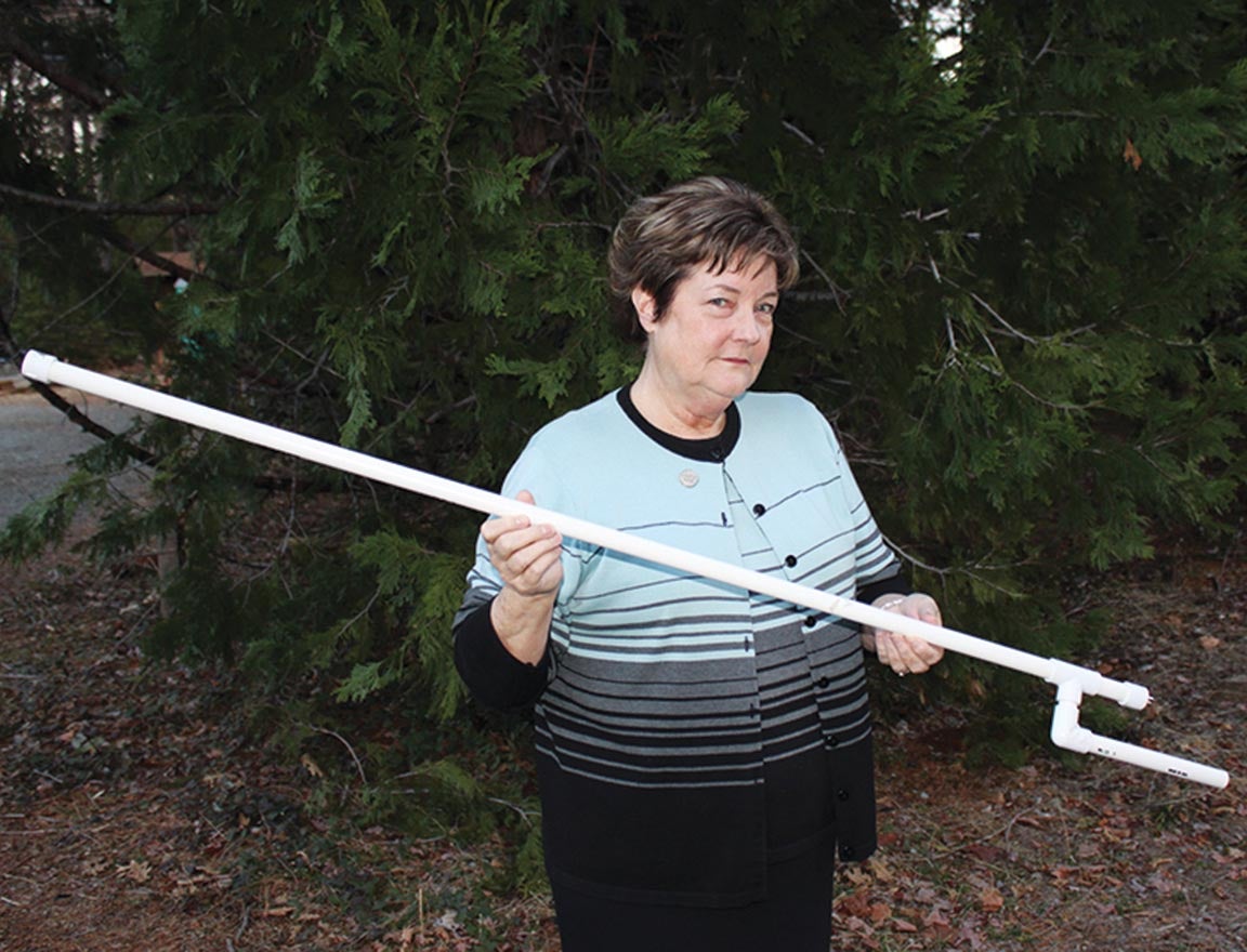
So let’s make a dipole antenna and see what we can figure out (same general principles apply to a ground plane).
What do we make it out of? Copper is near the top of the list because it’s cheap and readily available. What sort of copper? I’ve had the question, “Would a #40 copper wire strung across my glass canopy work?” The answer is yes, but not well. Why?
The answer is bandwidth. At the exact frequency for which the copper wire is cut, it will work well. It won’t work too well on either side of this frequency, and the answer is in what we call Voltage Standing Wave Ratio (VSWR—pronounced VIZZ-war). In a nutshell, the transmitter is trying to pump out power into the antenna and have it radiated. VSWR says, “No, I’m reflecting a certain amount of that power back because the antenna isn’t perfectly matched to the transmitter and coax.” How can that be?
 If you will recall from last month, we said that the impedance at the center of a resonant dipole is about 70Ω, and the center of a resonant ground plane is half of that, or about 35Ω. But we design our transmitters and coax to be 50Ω. Why? Because we will be feeding either a ground plane or a dipole, and we have to make the choice to split the difference so that the transmitter can drive either one with a little loss to either one. Calculating VSWR without a lot of mumbo-jumbo? Divide the big number by the small number. 70/50 = VSWR 1.4 or 50/35 = VSWR 1.4. See how that works? Again, without a whole lot of math, at a 1.4:1 VSWR, roughly 3% of the transmitter power will be reflected back down the line. For a 10-watt transmitter, this would be roughly 300 milliwatts. No big deal.
At the exact resonant frequency, this is so. But look what happens when we get to the band edges. I’m going to do the numbers for a ground plane; a dipole will be identical. At 127 MHz center frequency, sure enough, a #40 wire has a VSWR of roughly 1.4:1, but at the bottom com band end, it is nearly 3:1, and at the top end of 137 MHz, it is nearly 4:1. These are power reflections of 25% and 35% respectively—somewhere between a quarter and a third of your power is being reflected and beating your poor transmitter up pretty badly.
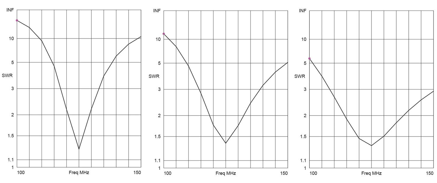
Now let’s take an antenna made out of half-inch copper tape. Center 1.4:1 VSWR is about the same, but at both band ends (118 and 137 MHz), the VSWR is below 2:1, which is a reflection of a bit less than 10%. That makes your transmitter a much happier camper.
Conclusion…for any antenna, fatter elements are better if you need an antenna to cover a large bandwidth.
So, we’ve talked about polarization, we’ve talked about ground planes and dipoles, and we’ve touched on baluns and coax. I think one more session on “floobydust” (baluns, coax, and other minor bits and pieces) and we can talk about building real antennas for our airplanes. Until then…Stay tuned…