Most of our aircraft have cables that need to have their tension properly set, an important ingredient in safe flight and flutter avoidance. Unfortunately, the tensiometer device employed to measure cable tension is usually quite expensive—professional ones typically in the neighborhood of $600 to $900, some simpler ones around $200, in any case a lot to tie up in a tool that will only be used a few times.
When I first completed my plane, I was able to borrow one from the local mechanic, but not without signing over the birth certificate of my firstborn, as he was exceptionally protective of the device, not to mention citing that recalibrations (if, for example, you were to drop it) are nearly as expensive as buying a new one!
So, when it came time to set/check my cable tensions again—they should usually be checked at annuals, and certainly if you take a cable apart you’ll need to measure and set—I decided to make my own tensiometer. The approach is simple and is detailed in the sections to follow. The core measuring device is an inexpensive but accurate dial indicator, which measures the deflection of the cable as it is pressed on by the spring-loaded plunger of the dial indicator.
Construction Details
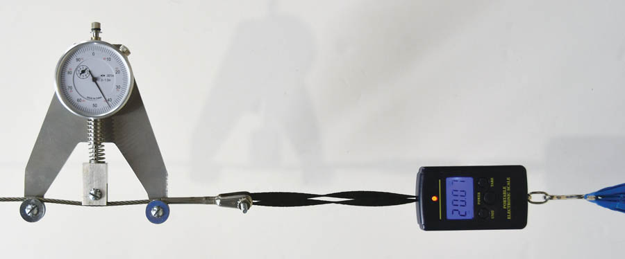
The basic mechanism is a 3/16-inch thick base plate on which are mounted two small ball bearings over which the cable to be measured passes, and the dial indicator, whose plunger has a compression spring on it that presses on the center point of the cable between the two bearings. The bearings allow the cable to move freely as it deflects slightly due to the spring force. The dial indicator shows the deflection of the cable. Actual cable tensions are determined from a table of deflections as indicated on the dial versus the corresponding tension, the data for the table having been determined by the device calibration described later.
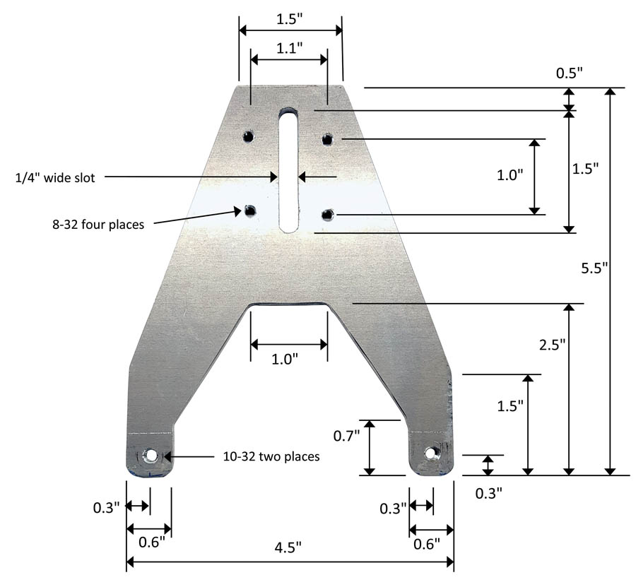
Figure 1 shows the various dimensions of the base plate and positions of the dial indicator and bearings as I built it. While the exact spring and its tension are not super critical, the details of the one I used are shown in the table of parts. Fundamentally, it needs to be a suitable diameter to fit around the dial indicator piston and have a compression K-factor that yields practical deflections of the desired cables.
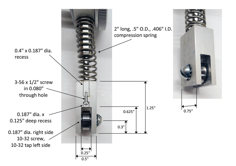
As supplied, the dial indicator has a small rounded end screwed into the piston. Key to the design is the replacement of this end piece with the small block carrying the ball bearing that will press on the cable. Figure 2 shows the details of that piece. It is attached to the dial indicator piston with a small screw. Unfortunately, measuring the threads on the end piece supplied with the dial indicator, I was not able to match it to any standard metric or SAE thread. However, 3-48 is close enough and holds the block adequately. Also, the piston diameter does not match any standard drill size perfectly either, but I found that a number 16 drill was very close and with a little bit of drill reaming was made to fit.
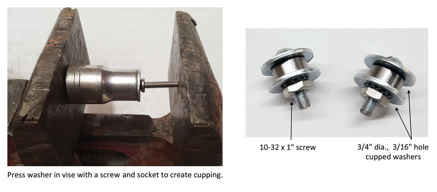
The three small bearings need to be wide enough to accommodate the thickest cables. The endpoint ones are simply mounted with screws and washers that act to retain the cable over the bearings. These washers need to be cupped slightly, with the convex side toward the bearings, such that the bearings may rotate freely. Figure 3 shows how I cupped the flat washers in a vise.
The dial indicator is mounted on the plate with a pair of angle brackets on the backside. (See Figure 4.) These are slotted, as is the base plate, to allow the dial indicator to be moved up and down to position the roller for an optimal meander path of the cable. This position will need to be determined interactively as a function of the spring chosen. The position in Figure 4 is shown for the spring specified.
Setup and Calibration
The spring on the dial indicator pushes the piston all the way out to the zero position on the scale. This can be set by rotating the dial cover. If you wish zero to be exactly at the top, this can be achieved by removing the top screw and inserting an appropriate thickness washer at the top of the indicator piston. Assembly of the tensiometer puts the unloaded position of the piston/bearing end past the straight through path of a cable, such that tension on the cable will then push the piston in and indicate the deflection on the dial. The greater the tension, the greater the deflection toward a straight line of the cable. Thus, the tensions that can be measured will depend on the force of the spring and the positioning of the dial indicator (and bearing end) on the mounting plate. The dimensions I have shown work well for typical 1/8-inch and 5/16-inch cables, and you may wish to vary these factors to give you a suitable range of dial indications. The fully extended spring space is about 1.6 inches. Therefore, the specified 2-inch long spring is compressed about 0.4 inch to start, for a preload of about 2.35 pounds. Therefore, the minimum cable tension that can be measured is that which produces a sideways force greater than 2.35 pounds to begin deflection of the dial indicator. For typical 5/32-inch cable and the device geometry shown, this is around 5 pounds.
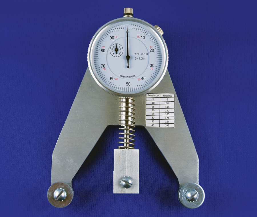
In any case, what is needed next is a calibration and a correspondence table for a set of cable sizes, cable tensions, and dial indications. I used several methods for calibration. One was to attach a piece of cable vertically, such as to the ceiling in your workspace, and to hang weights on the cable. Attach the tensiometer, then record the associated dial indications. If you trust a particular digital tension scale, you can attach that to the cable to apply “known” tensions, but I chose to “calibrate” a set of weights at the meat counter on their calibrated scales and hang them from the calibration cable. If you are a real stickler for accuracy, you can, of course, also include the weight of the cable piece that is below the point of measurement with the tensiometer! Alternatively, you can use a fish or digital pull scale on a benchtop with a suitable tensioning mechanism. While this is not quite as accurate, ultimately you will likely be setting a tension of something like 20 or 30 pounds, and +/-10% is not going to matter or be discernible. Figure 5 shows the tensiometer on a 5/32-inch cable with a tension of 20 pounds, along with my calibration table.
Use
The tensiometer is attached to the cable with a simple twist that routes the cable over the two bearings and depresses the indicator. I slide the tensiometer back and forth a slight bit for all the pieces to reach equilibrium. Then check your table for the dial indication for the desired cable tension, and tighten the cable to reach that number. Slide the tensiometer back and forth a bit again to neutralize the reading and make any further tension adjustments as needed.
EDIT 7/14/2022: The frame can also be 3-D printed. See Darrin Towers’ Thingverse files.

