We’ve talked in general terms about how to mount the electric motor from the Zero motorcycle into the eXenos and covered the electrical connections and wiring in detail. But what about all the fiddly bits? As anyone who has ever built an airplane knows, the devil is always in the details. So let’s look at a few of those details and how to make the motor fit the airframe in an electric Xenos!
In previous installments, I’ve talked about mounting the motor and fine-tuning the prop reduction drive (re-drive) components. Gabe DeVault’s system, which I’m using, is very simple, with a belt between the motor and the driven pulley plus a prop shaft cantilevered from a sturdy steel-tube mount that also hangs the motor. We also completed mounting the battery pack, a 180-pound beast that lies at the same 30° angle as the Xenos’ firewall.
With the battery mounted parallel to the firewall, that means that the pack, too, was tilted forward in the extreme, which would put significant twisting loads on the four bottom mounting bolts. Gabe solved this with a cross brace that the top forward of the battery pack leaned on, with the brace mounted to the two top tubes of the mount with Adel clamps. Sonex President (and CAD designer) Mark Schaible went one better in designing our mount—he added welded-on tabs attached to the two top tubes to which we could bolt the cross brace. This made for a much more solid and rigid structure supporting the battery.
There was one challenge in making this cross brace, the primary structure of which is simply a 1x1x1/8-inch aluminum angle. There are several screw heads along the top of the battery that protrude beyond the edge of the pack—meaning that the battery’s weight would be resting on those three screws on the cross brace. Not wanting to “point load” those screw heads, we made aluminum spacers for the inside of the angle that contact the actual edge of the battery and fit between the offending screw heads. We riveted the spacers to the angle for a permanent solution.
The aluminum angle cross brace was bolted to the welded-on tabs with standard AN4 bolts and nuts, completing the battery support structure and making it removable if that ever proves necessary.
Mounting the Charge Tank
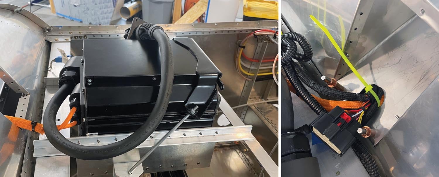
The charge tank is an optional high-speed charger provided by Zero for the motorcycle. It mounts in the empty (fake) fuel tank on the bike and was creatively designed by the motorcycle engineers to attach like a battery—it sits in a cradle and is held down with a mounting strap and two long J-hooks. This works really well on the bike but, unfortunately, provides no mounting flanges or hole with which to attach it to the aircraft. Our chosen location was behind the firewall, above the pilot’s and passenger’s legs, meaning that we had to figure out a way to suspend it there—making it a very interesting challenge.
The answer was to simply go with the flow and build an analog to the motorcycle’s cradle, then use the bike’s mounting strap and J-hooks. We did this by first installing a 1.5×1.5-inch aluminum angle across the cockpit, forward of the instrument panel, right where the original Xenos fuel tank strap mounts. We then fashioned two aluminum angles that spanned the space (fore and aft) from the top forward edge of the fuselage tub and that new cross angle. These two angles were the support members for a sheet metal cradle that fit the charge tank and suspended it in the space. We added bottom angle stiffeners to make the cradle very rigid, then riveted on aluminum angle “ears” where the J-hooks could attach. Riveted all together, it made a nice structure with no flex—a good way to mount the heavy charger. The cradle was bolted in place at the four corners to the cross-fuselage members, and the wiring from the front of the charger went through the opening in the firewall previously used by the fuel tank filler neck.
How To Build a Throttle
One of the things that didn’t feel quite right for me in the Xenos or Gabe’s
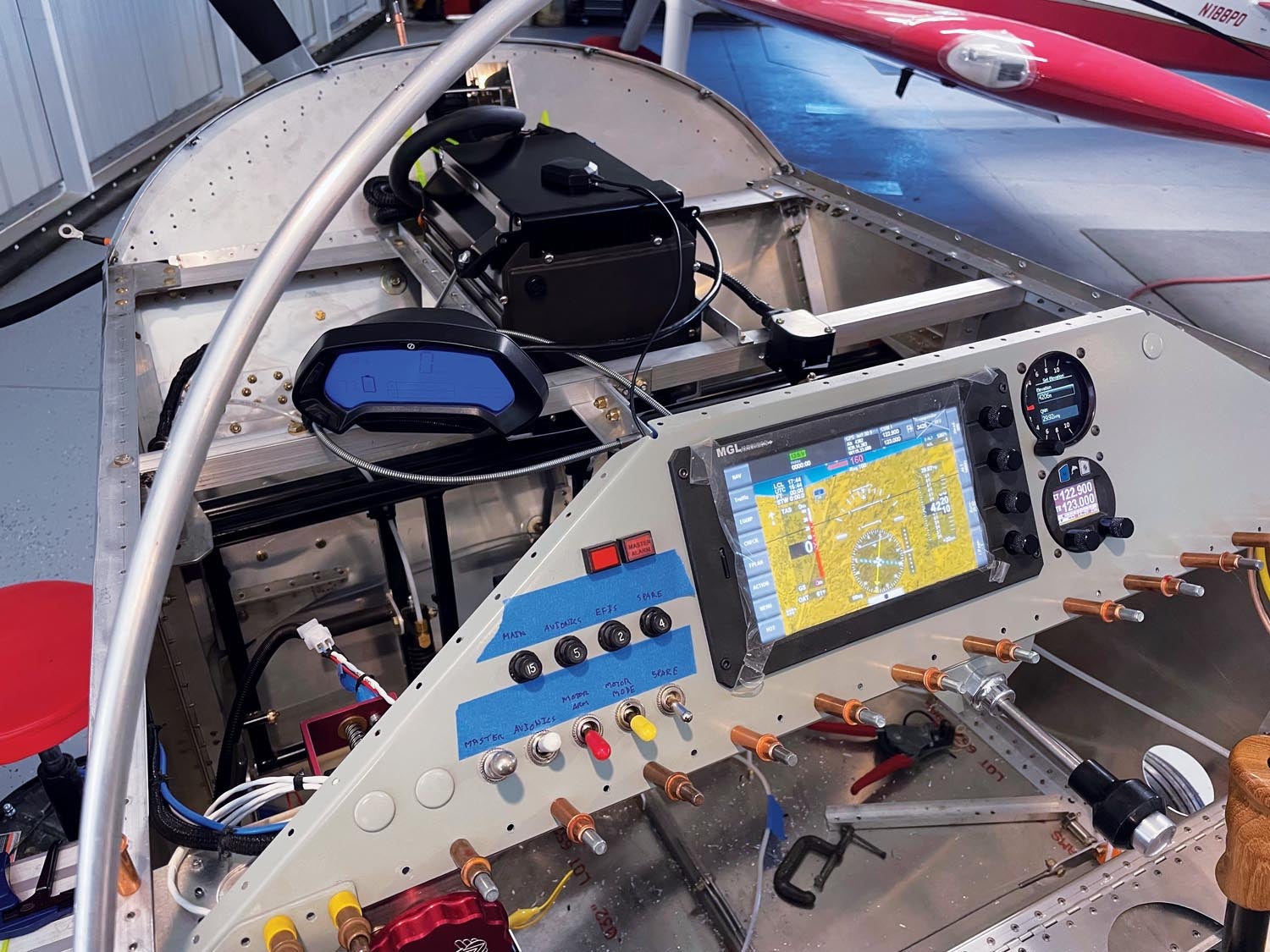
eXenos was the position of the throttle quadrant. It was a little crowded over on the left side of the cockpit. DeVault supplies a quadrant-style electronic throttle with his conversion package and I played with different places in the cockpit where it could go and be accessible to both seats yet not in the way. Hanging it under the middle of the panel was my initial thought until we tried getting in and out with it there—too cumbersome a process.
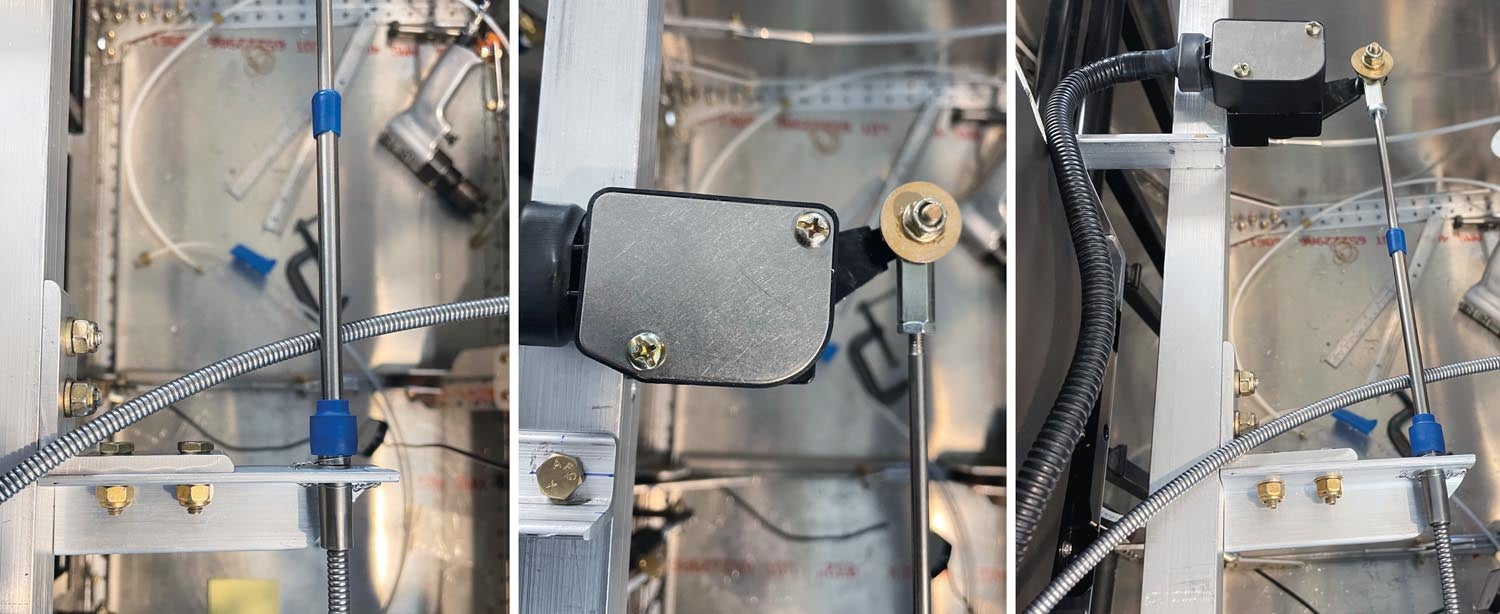
I eventually realized that a simple push-pull throttle, mounted under the center of the panel, would work just fine. Since much of the time we’d be flying as either a glider or wide open, the throttle wasn’t really that significant—so I created a hybrid. Using a vernier throttle (no, we’re not planning on flying formation) obtained from Aircraft Spruce to allow a precise power setting when we want to do power-assisted soaring, I mounted the quadrant behind the panel on the cross brace that holds the battery charger, then connected the end of the cable to the handle.
Of course, it wasn’t quite that simple. I played around with throws to determine the best distance from the lever pivot at which to mount the cable, then cut off the handle from the lever to allow edge distance from the hole. The cable was attached to the lever with a rod-end bearing and appropriate spacers to give it free motion. The cable body had to be mounted to a fork-shaped support, which was fabricated from aluminum angle. And finally, the pilot end of the throttle cable was mounted to a piece of angle that forms a subpanel under the instrument panel.
connected (right). The “throttle” is, of course, just an electrical device that tells the motor how fast to spin. Fly by wire!
Cooling Shrouds
Just because you don’t have an internal combustion engine, that doesn’t mean that you don’t have to cool the electric motor and its associated motor controller! Electric motors or combustion engines all generate heat with a byproduct being propulsion. That means you need some way to move air over both the motor and the controller, both of which are mounted under the cowling on the aircraft. You need inlets and outlets, but most importantly, you need to direct the air where it will do the most good—just like you do with baffling on a Lycoming, AeroVee or Jabiru. With those engines, you use metal baffling—with the electric motor, you can use a fiberglass shroud.
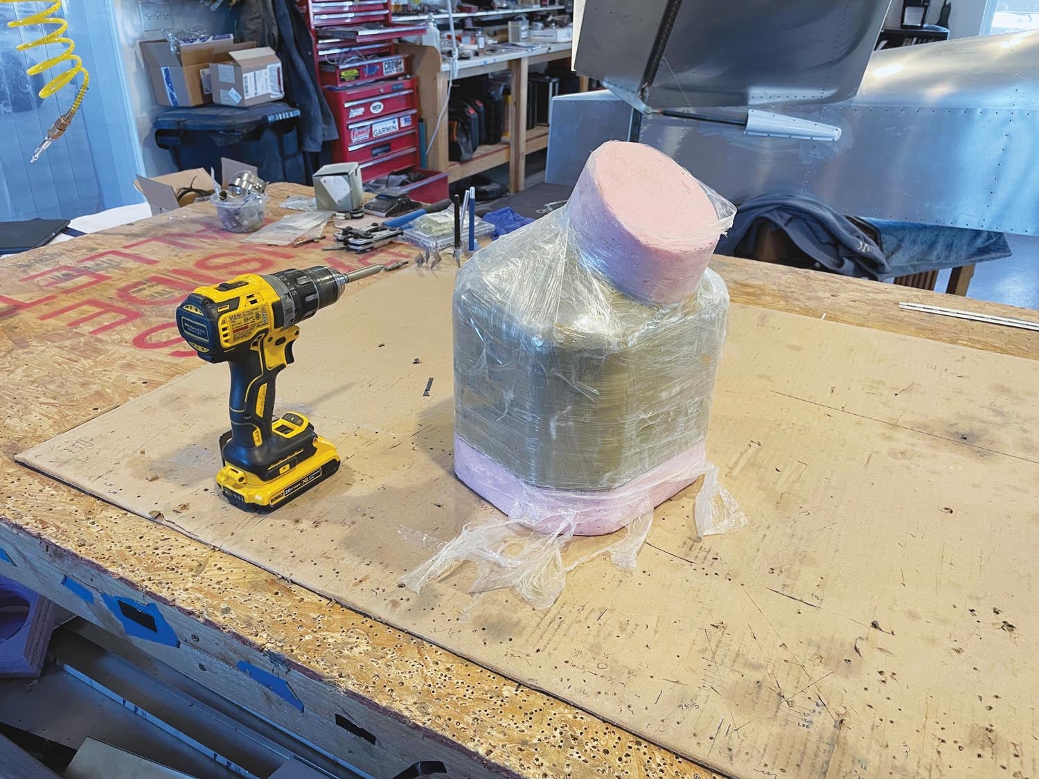
Fortunately, DeVault has pioneered the process with this installation. He designed a shroud shape in his CAD program that encloses the motor and provides an inlet as well as an appropriate opening at the back to direct air over the controller after it has passed through the motor’s cooling fins. He uses a CNC machine to carve the shroud shape out of high-density foam, wraps it in packing tape and pulls his shroud off that with fiberglass. And equally fortunate, he doesn’t destroy the plug in the process, so I was able to make my own shroud from the same mold.
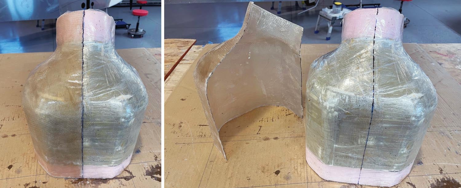
It isn’t rocket science—standard West System epoxy, several layers of cloth and mold release. That did the trick. Because the shroud needs to be installed and removable, it needs to be split in two halves—so I molded it that way. I drew a line down the middle of the mold and laid up one side first. I then carefully trimmed that half to the split line, covered it in tape and laid the second half up over the mold and the other side, forming a flange where the two halves meet. When that was cured, it was just a job of trimming it all for neatness before fitting it to the motor.
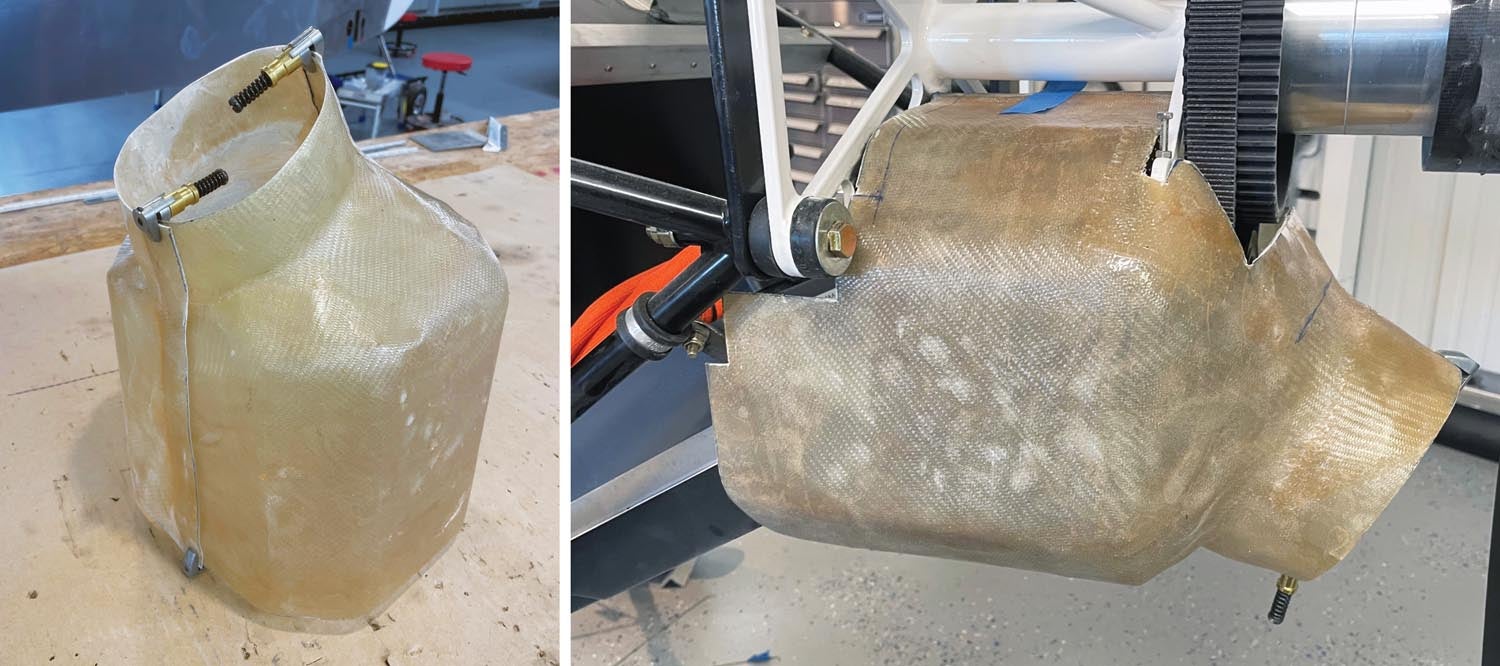
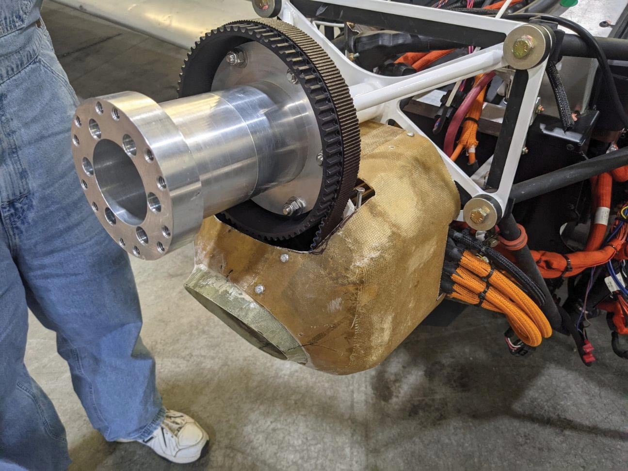
Fitting it to the motor required some creative measuring because you have to add openings for the mounting arms and the belt drive. There is no good way to describe this—you just have to look at a few pictures to get the general idea where the cuts will be and then start measuring and cutting a little at a time. If you overcut, you can always add epoxy and glass back on. The shroud mounts to four brackets made of sheet metal and is then mounted to the four lower bolt holes on the motor. These bolts are not used in the aircraft configuration since the motor hangs from the top four bolts—so you simply make the brackets, attach a #8 nut plate and attach them to the motor with 8mm metric bolts (the same types used for the motor mounting bolts). The shroud mounts to these brackets with #8 screws and drilling the holes is easy because the shroud is translucent. It only took me two tries to get them in the right place (and should you make a mistake, the shroud is very easy to patch.)
The final bit of work on cooling involved cowling modifications and, of course, this probably took the most time—mostly because the shroud didn’t need to look good, while the cowling is something everyone is going to see. But conceptually, the job is simple—and every perfectionist builder can make it as complicated beyond that as they wish. Basically, you need to plug the original cooling holes on either side of the propeller and then create a new cooling hole that lines up with the intake for the motor cooling shroud. Plugging the holes is pretty simple—fill the areas with blocks of foam and then epoxy and glass over them. Sand to taste.
The potential gotcha with the new cooling hole is that you have to remember that the motor (and therefore the cooling shroud duct) might move up and down by as much as an inch as you change belt tension. So take into account that your cooling hole needs to allow for this movement. We basically cut an oversized hole in the cowling (using tried-and-true trial and error) and then trimmed the duct back until it was essentially flush with the cowl. We then built a ring around that to trim out the hole, attaching it with #6 screws into nut plates mounted to the cowl. If the motor moves much, we can always make a new trim ring—packing tape, mold release and microballoons are your friends…
The Bottom Line
All in all, the best part about turning a Xenos into an eXenos is that from a mechanical modification standpoint, there is nothing outside the realm of the average set of homebuilding techniques. Cut and fit, use controls that are aircraft standard, bolt together aluminum and do fiberglass—all very normal stuff. You don’t need any special skills, like redesigning flux capacitors or fitting up small nuclear reactors. Electric propulsion is cleaner and simpler than internal combustion and, aside from having to work without (or draw your own) plans, the fabrication tasks are simple and straightforward. Good pictures of a previous installation (in our case, DeVault’s) are about all you need to get you going.
Program note: If you also go to the KITPLANES® website you know that the eXenos is already flying. But there are parts of the build process I want to go over in detail and that will take a couple more installments before we get to final assembly, inspection and first flight. At the risk of spoiling the surprise, the eXenos flies well (so far!) and has proven many of our small decisions to have been the right ones. —P.D.
Photos: Paul Dye and Marc Cook.


