 Typical EFIS systems will display most every engine or airframe data point you need or would like to see. However, sometimes you might like some additional info or a different presentation. Or, let’s say, you are happy with your steam gauges but would like to add some custom display features. In my case, I did not want to wait for the EFIS to completely boot up before starting the engine. I desired to see fuel levels to decide tank selection as well as fuel flow to set throttle position and count priming time. Additionally, I wanted to see the fuel level information in a more intuitive fashion than the EIS representation, namely a set of vertical bar graphs, in left to right positions, corresponding to the tank positions. The result was a custom color LCD display system that started out implementing these functions, but has since evolved to include a number of new homegrown features.
Such a custom display is a not a trivial design project. Here we will describe one particular system implementation for a particular set of features. Yours most likely will be substantially different, depending on what you would like to display and how you want it to look. This project may seem imposing and realistically will require some basic electronics and programing skills—but don’t be afraid to learn something new! And as you will see further on, these display devices include remarkable capabilities and support that make the job much less complicated.
Display Choice
Scouring what was available in flat panel displays, it became apparent there were three levels of integration. At the lowest are simple matrix displays with minimal low-level hardware support for pixel addressing and enabling. These require all higher-level functionality to reside in an external processing system, for example an Arduino, which in turn would also have to implement intermediate display hardware manipulation capabilities in firmware before application-level functions could even be considered. Displays at the next level include some of that display hardware manipulation firmware in hardware included with the display, but still leave at least application firmware to be housed externally. Displays at the highest level include all of the lower-level functionality as well as integrated processing to implement the full application, such that the display unit could conceivably be the complete system.
Additionally, there are OLED—organic LED—and TFT LCD display types. The former are brighter, but unfortunately are not readily available in sizes much over 1.5 inches diagonal. I was looking for around 3 to 4 inches diagonal, so LCD it was. Finally, the company I found, Australia’s 4D Systems, features a comprehensive line of fully integrated displays ranging from 2.4 to 7 inches diagonal, 240×320 to 480×800 pixels resolution, with multiple A/D inputs, multiple discrete I/Os and an incredibly broad set of firmware features, making it relatively easy to build your system.
Display Unit Hardware and Software Overview
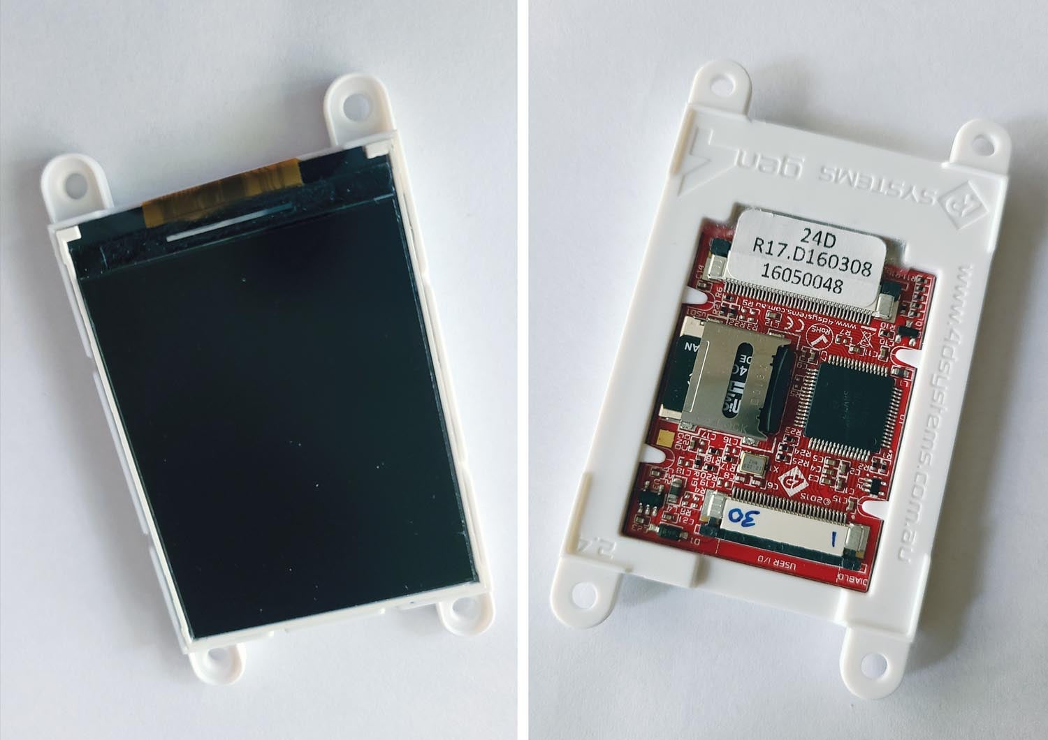
The display unit chosen is the gen4-uLCD-35D, which is a non-touch basic version. This display is also available in resistive or capacitive touch, and with a bezel. It features a 3.5-inch color TFT LCD display with 320×480 resolution and RGB 65K “true to life colors.” The onboard Diablo 16 embedded graphics processor provides a mind-bogglingly rich and comprehensive high-level instruction set for graphics, math (including floating point), I/O, text, memory management, sound and much more. The display includes a micro SD card slot for storage of images, video and audio files, and there’s a highly detailed 554-page instruction set manual, which includes examples for each instruction.
Development Environment
To further simplify the development effort, 4D Systems offers a hardware interface card, which connects to a USB port on your computer, as well as providing direct access to all the display’s I/O interfaces. On the computer side, there is a free comprehensive firmware development system providing three levels of possible development. The highest includes numerous widgets and precooked graphic designs for various components such as gauges, meters, etc. The lowest level allows you to create all your own graphics. I chose the low level because I had specific ideas about what I wanted all the graphic components to look like. The graphic support in the instruction set, even programming at the low level, is so good that it is still very easy to create display items with minimal code. We’ll have some examples later.
Hardware Design
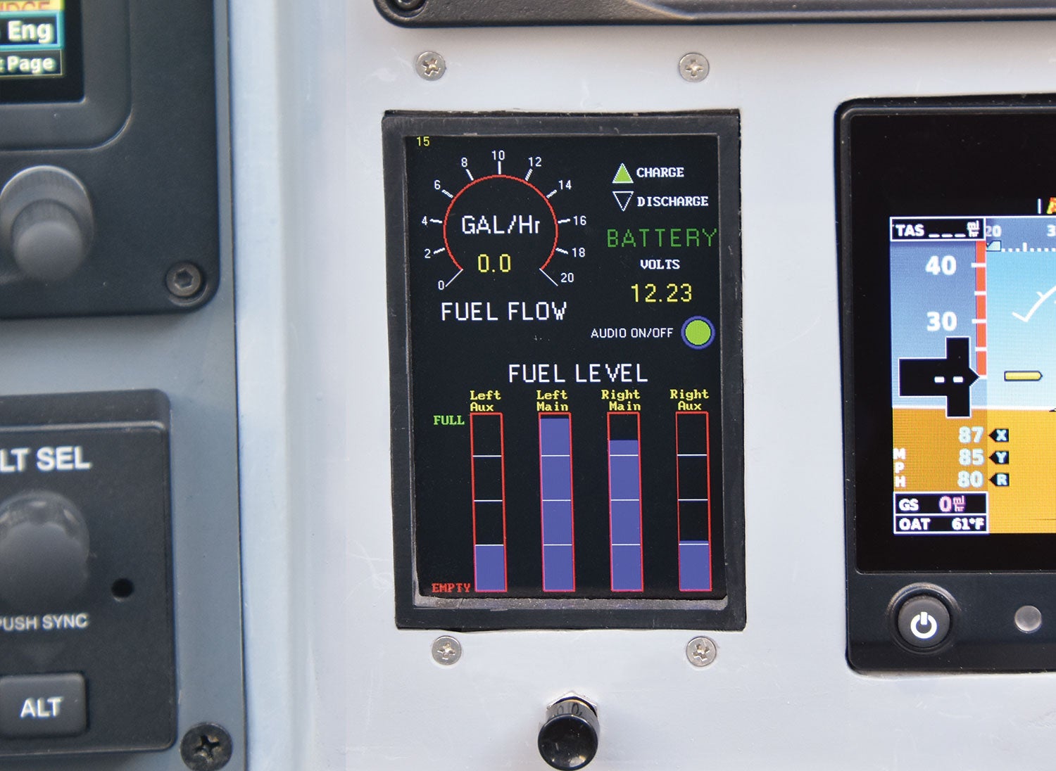
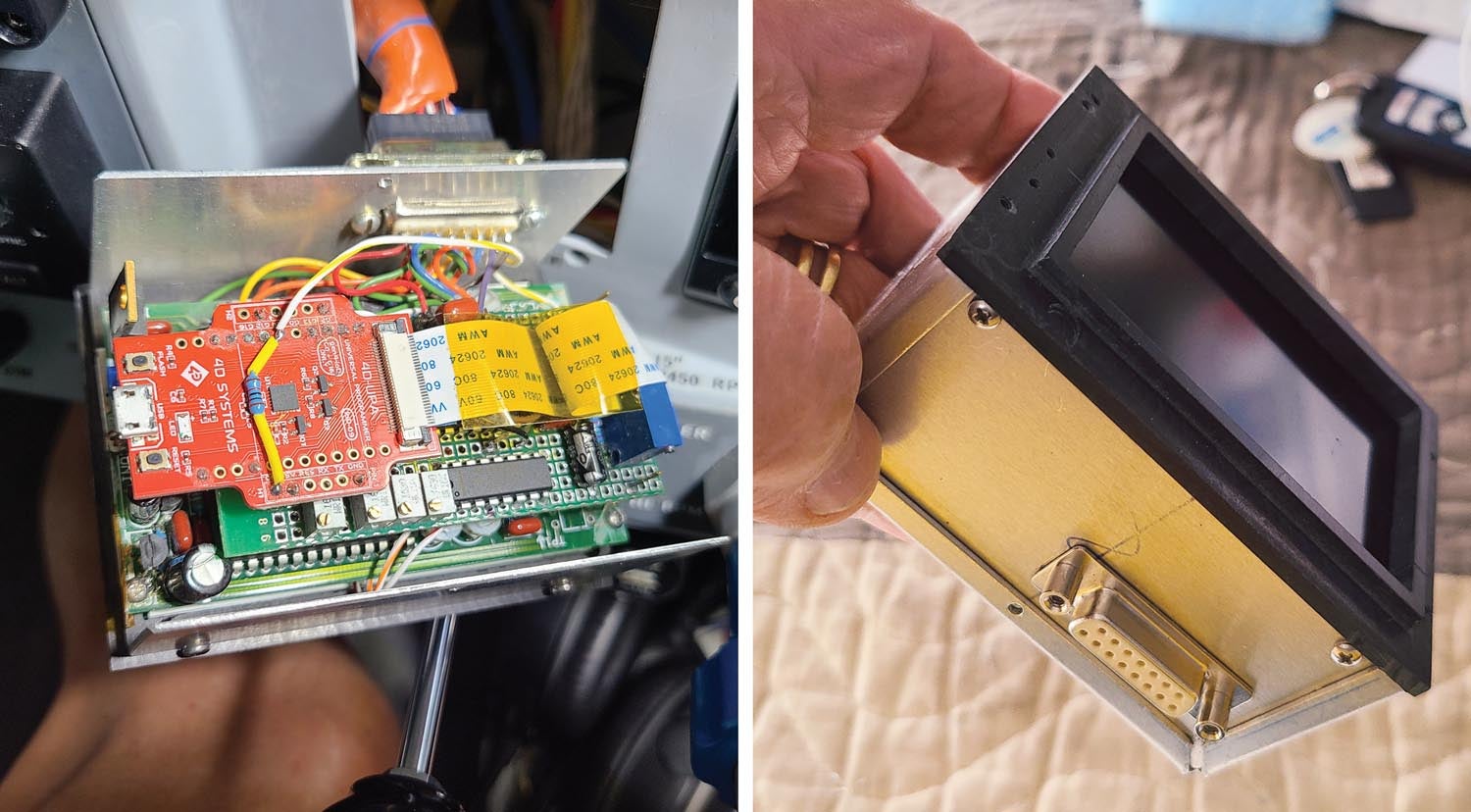
My display items were four fuel-tank levels in vertical bar graph form and fuel flow in gallons per hour in a circular gauge. Battery voltage is shown, along with battery charge/discharge information, and there’s an audio alert on/off indicator. Take a look at the photo for a view of the completed display.
Here’s the format of the input data: 0 to 5 volts for each of the fuel tanks, fuel flow is pulses from the fuel-flow sender, and actual bus voltage is used for battery volts. The audio alert on/off is from a momentary push button, and the battery charge/discharge is a 0/1 binary input from a custom comparator circuit of my design, which looks at which direction current is flowing in the battery ground strap. (This is a positive indication of health of the battery/alternator community, as the direction of current in flight should never be discharging—the alternator should always be providing all the load current. The battery should only be charging after engine starting, with discharge due to the plane having sat for some time or operating electrical loads without the engine running.)
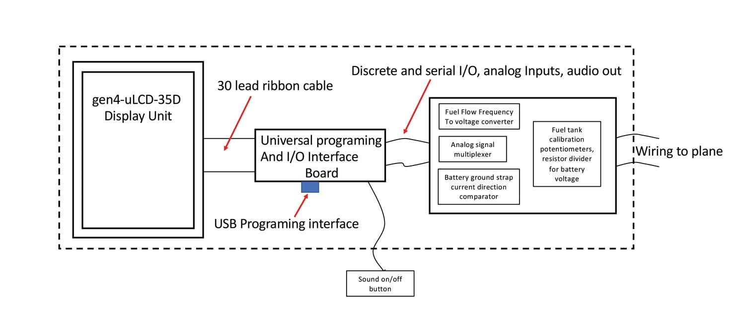
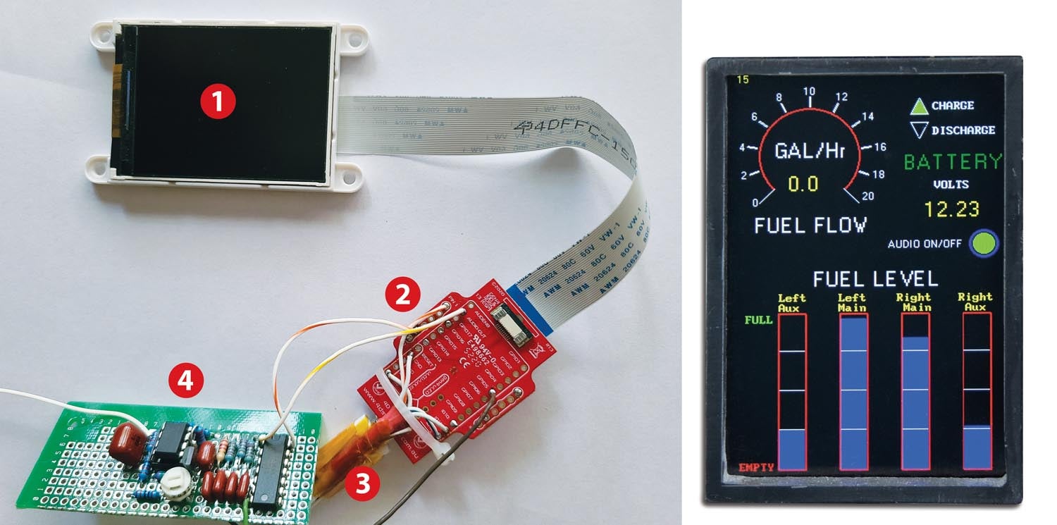
The 4D display provides four analog-to-digital inputs. The fuel tanks, battery voltage and fuel flow are six analog signals, so an external analog multiplexer was needed. In addition, since the fuel-flow data is a variable frequency pulse train, a frequency-to-voltage converter was needed. All this added up to the total system hardware consisting of the 4D display plus the 4D I/O adapter board and my added interface hardware on a separate small board. See the system hardware block diagram and photo of the completed unit for details. Again, the intent here is not for you to necessarily build this exact same design, but rather to learn how you can create a design of your own for your particular display items.
Firmware
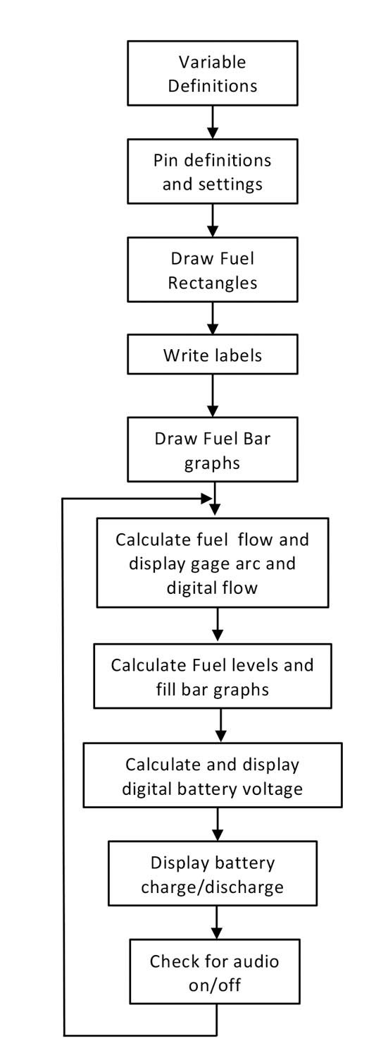
Take a look at the high-level block diagram of the firmware design. The actual code is here. In any case, the process of writing code is greatly simplified by the excellent 4D examples and extensive application notes organized by typical functions. Without going into the details of the entire firmware for this design, let’s examine a couple of the pieces of the design to see how simple it is to create a display.
The fuel tank graphic consists of four vertical rectangles, each having a red outline, three white separator bars and a blue fill for the level. Here’s what it takes to create the red outlines: In the Diablo16 code set there is a graphics instruction “gfx_Rectangle(x1, y1, x2, y2, colour).” (Yes, that’s how they spell color—remember, this is an Australian company!) You simply supply the coordinates of the lower left and upper right corner and color code for the desired rectangle and, voilà, it’s done. So, for the outline of the four fuel gauges there are four such instructions. Of course, you need to do a bit of homework to figure out those rectangle coordinates in terms of where they should end up in the 320×480 pixel display. But the development environment makes this super easy, as you can write code, load it into your display in seconds and see what you’ve got, and interactively modify and incrementally grow your code base one piece at a time.
Similarly, the fuel flow gauge semi-circular red line is created with one simple “gfx_RingSegment(x, y, Rad1, Rad2, starta, enda, colour)” instruction, in which you supply an x-y center coordinate, an inner and outer radius, a start angle, an end angle and a color. This is an example of the richness of graphics instructions available to let you do just about anything for your desired display look—and also an example, once you get the hang of it, of the simplicity of creating graphics on these displays. Text creation is also simple: a location instruction, followed by an instruction that includes the text, font, size and color. And just like that, it appears on the screen.
Mechanical and Installation
Notice the bezel in the photo of the completed unit. I created it to match other items in the panel by machining it out of black Corian. The display is mounted in a recess in the back of the bezel, and the outer flange has tapped holes for screws to mount the unit through the panel. A bent aluminum cover completes the housing.
Growth Features
Once you have such a capable home-brew item in the panel, you can think up additional functions to add. If the I/O capacity is still available, say for an additional serial port, then functions and displays can be added with the appropriate re-layout of the graphics. For example, I am currently working on an affordable radar altimeter feature, which will have the sensor hardware mounted in the bottom of a wing access cover, communicating with the display through a serial link. The remainder of the needed functionality is easily provided by some additional programming for a height readout on the display, which I may omit—just audio callouts are probably preferable. That’s the beauty of these devices; they include sound capabilities, with instructions to play prerecorded WAV audio files (e.g., “50 feet,” “40 feet,” etc…) to a pulse width modulation (PWM) output that just needs some external filtering to send it to a miscellaneous input on your audio panel. Using this feature, I’ve already added some audio alerts that announce low or high battery voltage and battery discharge. The data for these was already there in the unit, and all that was needed was additional code and the appropriate WAV files for the audio, stored on the micro SD card.
![[Credit: Radiant Technology]](https://www.kitplanes.com/wp-content/uploads/2026/04/550095_5165745cc27748a598699799d796fd94mv2.jpg?w=218&h=150&crop=1 "Radiant Technology Unveils SafeGyro")


Do you have a rating of the display brightness? Most graphic displays I have used are not daylight readable. For a trim indicator, I finally went with an e-paper display but their update rate is measured in seconds!
I have encountered the same issue and found e-paper to be slow and also wanted backlighting – one solution I tried was using dual OLED displays side-by-side. That worked but still, there are some issues/limitations with that. I am also investigating a couple of daylight-readable TFT displays I was able to find. The biggest issue is keeping the cost down on these types of displays! Another problem is getting something I can integrate into – I prefer to use an ESP32 and do not want my display to use every IO I have.
Hi,
This brightness issue is a tough one. From my testing, 800 nits seems to be the bare minimum for actual sunlight readability—probably close to what Garmin uses, though I haven’t found published specs. Truly outdoor-readable displays, like those at Disneyland kiosks, tend to be in the 1000–2000 nit range.
Displays like that are notoriously hard to source in small quantities. Almost no hobbyists are doing this kind of work, which makes it even harder. For now, I’m starting with Adafruit development boards (plus some AI coding help), just to get something working. Once I’ve got a functional prototype, I’ll tackle the high-brightness dragon later—otherwise I may never get started.
Not 70, by the way—just 61. We’re not all that way yet!
Great article, and very timely.
—Matt
You are right, this display is not as bright as my Garmin screens, and when hit with direct sunlight I usually end up holding my hand to shade when I want to read it, and without direct sun, it is a bit dim, but readable. I mounted this a bit low on the panel, which helps. At night, it is perfect!
These LCDs are backordered almost 1 year. What is an alternative LCD option to experiment with? Is there a name for the different levels of LCD displays based upon the level of integration? What would I search for to find comparable LCD screens to try?
Thanks
At Mouser they are on a 13 week lead time. Other sizes, like the slightly larger ULCD-43 are readily available.r
I’ve been looking for display just like this and lo and behold I came across your excellent article “Build a Custom Display” gave me inspiration to try to build one for my RV6 panel. Going to order SK-GEN4-35D Starter Kit for first-time users, the “application-specific external circuitry”, is this included with the kit, or it needs to be order separately? if so, could you share the part number and where you purchased it from.
The universal programming and I/O interface board is also from 4D Systems. But the remainder of the circuitry in the article for the fuel gauges and fuel flow were all custom discrete designs that I came up with, and typically would be your own as well as they depend on your specific needs, signal levels and formats, etc.
Reinhard Metz
Thanks very much for this article. I bought a starter kit and was able to prototype a CDI display with it after a week or so climbing the learning curve. (The Garmin GNC 255, as an example, outputs a NMEA-formatted CDI message, the $PGRMV21 message, which can be used to drive such an instrument.)
For those building custom displays that the 4D Systems widgets don’t completely support, and interfacing to an Arduino or similar microcomputer, I recommend their AN-100.
What a great article. This is precisely what is needed to lower the seventy plus year average age of the local EAA Chapter meetings I attend occasionally. Articles like this will help bridge the gap between those who would rather relive the golden age of aviation and those who can now build the golden future of aviation with cutting edge production tools and knowledge available at little or no cost to pretty much anyone. I believe it is that bridge combining the knowledge of the old with the modern methods that will move us forward together. I will build your display and use it to hopefully motivate others just as you have encouraged me. Thank You
Tom, thanks for your kind comments! Ironically, I am actually one of those 70+ aviator types, but can’t help doing this kind of stuff! BTW, 4Dsystems still makes this particular display, but seems to have gone to some considerable effort to move the instruction manual and data sheet info to other places on their website, so you may need to hunt a bit, or let me know and I can send my pdf versions.
Reinhard Metz
Comments are closed.