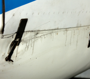
Yep. You have an oil leak. But where is it coming from?
I’m not aware of an established classification for oil leaks like there is for jet fuel leaks, but I do know that there is a difference between oil leaks and oil seeps. Seeps are small, and they are confined to the engine compartment. Leaks are visible outside of the engine compartment and can range from a pencil-lead-size wind-blown trail to a gusher that requires an immediate landing. Gushers can’t really be classified as leaks because they are almost always a symptom of a more serious engine problem.
Seeps are the result of gaskets, hoses and seals that no longer seal due to poor or incomplete installation, age, heat, vibration or a combination of these factors. The most common causes of leaks are gaskets that no longer seal, mishandling of parts such as pushrod tubes in small Continental engines, worn rocker box return tubes, cracked or stiff hoses, and broken fasteners such as case through bolts and cracks in the case.
The Sump
An FAA rule related to engine oil capacity in FAR 23 Section 1011(c) says that "The usable oil tank capacity may not be less than the product of the endurance of the airplane under critical operating conditions and the maximum oil consumption of the engine under the same conditions, plus a suitable margin to ensure adequate circulation and cooling."
What does this mean? Simply put, the oil sump on your engine has more capacity than is needed for normal operations. The large sump acts as a sort of insurance that protects the engine manufacturer if an airframe manufacturer makes an airframe with a very large fuel capacity.
Because of this generous sump capacity, topping off the oil causes the oil level to go down rapidly-until the engine reaches its equilibrium (for lack of a better term). Oil in the sump greater than the equilibrium level is blown out through the crankcase breather tube thanks to normal positive pressures within the crankcase. The equilibrium level varies from engine to engine, but one example is the Teledyne Continental 230-horsepower O-470 engine in the Cessna 182. Most variations of this engine have a 12-quart-capacity sump and an equilibrium level of 8 to 9 quarts. You can tell when your engine reaches its equilibrium when the oil level stabilizes. Under normal conditions (no aerobatic maneuvers) aircraft engines are safe to operate with the oil sumps half full.
Use It and Lose It
Before we delve deeper into oil leaks, let’s take a moment to discuss oil consumption. Airplane engines use oil. It’s not unusual for them to go for years consuming a quart of oil every three to four flight hours. Consumption at this rate is not a strong signal that the end is near. It’s been said that oil consumption only becomes excessive at 1 quart per hour. Not true-that’s too much, according to both Lycoming and Teledyne Continental Motors (TCM).
Lycoming Service Instruction SI1427B defines excessive oil consumption with the following formula: 0.006 x BHP x 4 ∕ 7.4 = quarts/hour. Let’s plug in 75% power (a common cruise power setting) for the Lycoming 180-hp O-360; 75% of 180 hp is 135 hp. Inserting this value into the equation yields 0.006 x 135 x 4 = 3.24. Divide this by 7.4 and you get 0.43 quarts per hour as maximum oil consumption. Inserting the numbers for a 75% power setting for the 260-hp IO-540 yields a maximum hourly oil consumption of 0.63 quarts per hour.
The TCM equation produces a result in pounds, whereas the Lycoming formula yields gallons. The TCM equation is: (0.006 x BHP) / 100 = pounds/BHP/hour. For example, a TCM IO-520-BB engine is rated at 285 hp and 75% power is 214 hp. So 0.006 x 75% = 0.006 x 0.75 = 0.0045 x 214 BHP = 0.96 pounds/hour.
One quart of oil weighs 1.875 pounds, so the maximum allowable oil consumption would be 1 quart every 2 hours at 75% power.
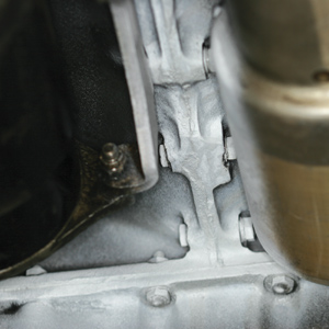
Using spray-on developer intended for dye-penetrant inspections can help disclose the source of oil leaks.
Leak Detection
Locating the leaking joint, crack or gasket requires discipline and experience. The inexperienced think all that’s needed to locate the source of an oil leak is to find the spot directly above the oil spots on the cowling, but it’s not that easy. Oil seldom drips straight down-it’s blown to and fro due to the hurricane-force hot and cold air currents that swirl between the cowling air inlets during flight.
Film captures of under-cowling airflow tufting have proven that an orderly flow of cooling air from entrance to exit is rare. In some cases, air flows back toward the entrance instead of following the manufacturer’s planned route.
The most important weapon in all leak-busting toolboxes is the human eye. Give the outside of the cowling a thorough visual inspection after every flight, always bending down to examine the belly aft of the engine crankcase breather tube.
Crankcase Pressure Too High?
Any change in the crankcase breather tube oil discharge rate needs to be investigated because the tube vents the engine case. Engine case pressures are a prime indicator of engine health. When excessive oil is blowing out the breather tube and covering the fuselage aft of the tube, excessive crankcase pressures may be the cause.
Teledyne Continental Motors recommends a method for measuring the pressure inside its engines: Buy a spare oil dipstick cap, and modify it with a fitting so that a hose can be connected to the cap. Connect one end of a flexible hose to the cap and the other end of the hose to an airspeed meter or manometer that measures inches of water. On the ground, with the engine at operating temperature and at full power, note the crankcase pressure. According to Teledyne’s Service Bulletin M89-9, the maximum on-ground crankcase pressure in small-bore TCM engines such as the A-65 C-series (including the C-145, O-200, O- and GO-300 and IO-346) is 1 inch of water, or 44 mph on a calibrated airspeed meter. The maximum limit for big-bore TCM engines such as the IO- and TSIO-360, I- and IO-470, all 520 and all 550 series engines is 4 inches of water, or 90 mph on the airspeed meter.
Lycomings should indicate between 45 and 55 mph, but not more than 100 mph.
Why all of this insistence on paying close attention to breather oil discharges? It’s simply because the breather tube is an easy-to-check engine health diagnostic tool that is often ignored. Monitor it for changes after each flight.
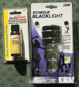
An inexpensive kit made up of UV dye and a black light can really shine a spotlight on leaks.
OK, so you found the sweet spot in your oil level, and the amount of discharge from the breather tube hasn’t changed. But you know there’s an oil leak. How bad is it? Leaks range from a couple of threads of oil trailing aft from a cowling skin to a significant leak. If bigger leaks aren’t fixed, soon you’re liable to hear a line boy telling you that your tail cone is leaking oil.
Even though I’ve already said that under-cowling airflows can yield some strange dispersion patterns, it’s important to pay close attention to the oil pattern on the cowling during removal. Which side is it on? Is the oil on the upper cowling, lower cowling or both? Is most of the oil on the left side, the right side or both? Is it evident at the front of the engine or at the back? These points carry some weight, but they may be red herrings due to the effects of under-cowling airflow in flight.
Once the cowling is removed and safely stored, get a stool about engine height, grab the brightest flashlight you own, sit down, and start looking closely at the engine installation. You’re searching for obvious leak sources such as missing hardware, loose parts such as the dipstick tube on a Lycoming engine, parts rubbing against other parts such as an engine baffle tie rod rubbing through a Lycoming upper cylinder oil return tube, crusty looking hoses "pooched out" from under clamps that have been tightened in quick-and-dirty attempts to stop leaks and other obvious sources. Go slowly and wipe clean often. Fix anything that looks marginal or raises a question. If an obvious leak source is found, make an airworthy repair.
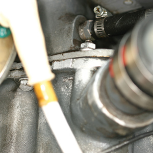
Common leak sources include the oil pan/case split, but you should also be watchful of those rubber couplings on the oil-drainback tubes.
Some technicians suggest that leaks can be found by spraying soapy water around suspected leak sources after pressurizing the engine case with air pressure (no more than 1 psi) and using the fitting developed for the crankcase pressure test. I haven’t had much success with this on little leaks. If you use this method, make sure to limit the pressure lest you blow the crankshaft oil seal out of position.
Clean, Clean, Clean
One time-tested method for cleaning engines is drawing Stoddard solvent up into a siphon gun that is connected to an 80- to 120-psi shop air source, and blowing the solvent on the engine. This method is still used in many shops for overall cleaning or spot cleaning. Note: Before using any sprayed cleaners, cover the magnetos, vacuum pump, and the carburetor and induction air inlet with tin foil or plastic bags.
Some stains are stubborn and may require scrubbing with a fiber, stainless-steel or brass brush. After the stains are removed, the engine is dried with compressed air.
Today there’s a move toward using biodegradable cleaners that are readily available from aviation supply houses or auto parts stores. These are applied using either the squeeze bottle the product came in, or they’re sprayed on using a siphon gun. Follow the manufacturer’s instructions, and then wash the engine clean with a water stream. Castrol Super Clean and Extreme Simple Green Aircraft are two products that are known to work well. Again, don’t forget to cover both magnetos, the vacuum pump and the carburetor or fuel injection air inlet filter during cleaning, water spray and air drying operations. Heavy-duty aluminum foil works well for this purpose.
Powder or Light
After the engine is completely dry, run it on the ground for a few minutes and visually check again for leaks. Part of the oil leak detection dilemma is trying to determine how long to run the engine. You want to run it long enough for the leak to be seen but not so long that excessive leakage clouds the source. Too long and you’ll have to clean again. Too short a run doesn’t let the leak develop, likely because the oil didn’t get hot enough. Trial and error is the only way to determine what engine run time works best.
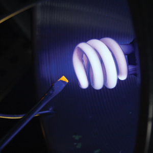
Eco-friendly and useful, the compact fluorescent black light shows how the dye, visible on the tip of the screwdriver, is really obvious.
There are two common leak-detection tricks. The first consists of spraying the suspected leak area with powder. I’ve heard that spraying or brushing talcum powder works-but I use a spray-on developer for dye penetrant inspections. I bought a can at the local weld shop for less than $10 and sprayed the white developer on the split line of the right and left engine case halves in a quest to find a pesky leak. It was easy to see that there wasn’t any oil on the split line after a run, so I washed off the developer. I later located the leak using fluorescent leak detector dye and a black light.
To do this, add a little dye (I found some at the local auto parts store for less than $8)-used in a ratio of 1 ounce to 5 quarts of oil-to the engine oil and then run the engine. Under a black light (also called ultraviolet or UV light), the dye will glow yellow/green. I bought a 110 VAC powered black light, but if I’d had more time, I would have purchased a portable or flashlight style light that you can find on the Internet. Unfortunately, some leaks are due to cracks in the engine case halves. In almost all instances, repair requires disassembly of the engine.

![]()
Steve Ells is what you call a gen-u-ine mechanic, a bonafide A&P with an Inspection Authorization. Former West Coast editor for AOPA Pilot and tech guy for the Cessna Pilots Association, Ells has flown and wrenched on a wide range of aircraft. He owns and wrenches (a lot!) on a classic Piper Comanche. But don’t hold that against him.

